BR/TS-80-IIB3
Detonation Flame Arrester for tank ships and containers

Features
Meets all ADN* Requirements
* European Agreement concerning the International Carriage of Dangerous Goods by Inland Waterways
Calculation of Loading and Unloading Rates
We offer Support in Calculating Loading and Unloading Rates
Emergency Venting
with the flexibly mounted Flame Arrester enables use even in Bad Weather Conditions as well as with Contaminated Products
Flat Design
Modular Design
Allows Replacement and Cleaning of Single FLAMEFILTER®
Spare Parts
Cost-Effective Spare Parts
For Flammable Liquids
Useable for Nearly All Flammable Liquids
Maintenance and Cleaning Hatch
May be used as Maintenance and Cleaning Hatch
Function and Description
Protection of Tanker Ships and Containers
The
Pressure/vacuum relief valve
Pressure/vacuum relief valve is an umbrella term that includes pressure or vacuum relief valve as well as pressure and vacuum relief valve.
PROTEGO® BR/TS-80-IIB3
Detonation
Detonation
Explosion propagating at supersonic velocity and characterized by a shock wave (EN 1127-1: 1997).
Flame Arrester
Flame arrester
Device fitted to the opening of an enclosure, or to the connecting pipe work of a system of enclosures, and whose intended function is to allow flow but prevent the transmission of a flame.
was developed for protecting tankships but can also be used for containers. These devices are especially used on tank ships operating on inland waterways or coastal shipping. The
device
Device
A device is a pipe component that influences the media flow by opening, closing, or partially shutting off the flow channel or by dividing or mixing the media flow.
is installed on the tank or a pipe section connected to the tank with a
nominal size
Nominal size
The nominal size is an alphanumeric designation of size for components in a piping system, used for reference purposes, comprising the letters DN followed by a dimensionless integer that is indirectly related to the physical size of the bore or outside diameter of the connections, expessed in millimeters.
of 250 mm / 10" and connected to the vapour balancing line (DN 80 / 3"). The individual tanks connected via the vapour balancing line are technically decoupled by the
detonation arresters
Detonation flame arrester
Flame arrester designed to prevent the transmission of a detonation.
and protected.

Main Component – PROTEGO® Flame Arrester Unit
The device protects against unidirectional detonation. In particular, the arrester consists of a
shock absorber
Shock absorber
A shock absorber is a device that reduces the kinetic energy of a detonation.
(1) and the PROTEGO® Flame Arrester Unit (2). The PROTEGO® Flame Arrester Unit consists of several FLAMEFILTER® discs (3) and spacers fi rmly held in a
FLAMEFILTER® cage
FLAMEFILTER® cage
The FLAMEFILTER® cage is a housing for a FLAMEFILTER® set.
(4). It is moveable and can be folded to the side for
maintenance
Maintenance
Combination of all technical and administrative actions, including supervision actions, intended to maintain or restore a unit in working order.
. The primary goal of this design is to enable the tank to be vented or supplied with air in an emergency when ice or crystallizing products clog the FLAMEFILTER®.

For Explosion Groups IIA to IIB3
The PROTEGO® BR/TS Flame Arrester is available for
explosion
Explosion
Abrupt oxidation or decomposition reaction producing an increase in temperature, pressure, or in both simultaneously.
groups IIA to IIB3 (NEC group D and C MESG ≥ 0.65 mm).
The standard design is approved up to an
operating temperature
Operating temperature
Temperature reached when the equipment is operating under design conditions.
of +60°C / 140°F and an
operating pressure
Operating pressure
Operating pressure is the pressure existing at normal operating conditions within the system being protected.
up to 1.55 bar / 22.47 psi (absolute), and it meets all the conditions of the ADN* for hazardous goods transport on European Inland Waterways.
EU conformity according to the currently valid ATEX directive. Approvals according to other national/international regulations on request.
Product Data
Material selection for housing
| Design | A | B | |
| Housing Housing A housing is a solid shell, which surrounds a content, either protecting the content from external influences, or protecting the environment from the content. | Steel | Stainless Steel | |
| Cover | Steel | Stainless Steel | |
| Gasket | Tankatite | Tankatite | |
| Flame arrester unit Flame arrester unit Flame arrester casing with FLAMEFILTER® set. | A | A |
Material selection for flame arrester unit
| Design | A |
| FLAMEFILTER® cage | Stainless Steel |
| FLAMEFILTER® | Stainless Steel |
| Spacer Spacer The spacer is a component that is generally used in a PROTEGO® flame arrester as a spacer within the FLAMEFILTER® se | Stainless Steel |
Flange connection type
| EN 1092-1; Form B1 |
| ASME B16.5 CL 150 R.F. |
other types upon request
Flow Capacity Chart
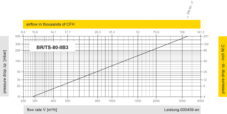
The flow capacity charts have been determined with a calibrated and TÜV certified flow capacity test rig. Volume flow V in (m³/h) and CFH refer to the standard reference conditions of air ISO 6358 (20°C, 1bar). For conversion to other densities and temperatures refer to Sec. 1: “Technical Fundamentals”.


Contact CSR Department
