FA-I-PTFE
In-Line Deflagration Flame Arrester concentric design, bidirectional
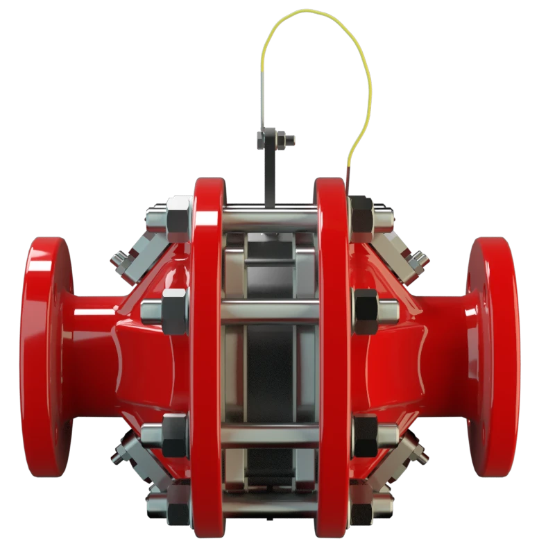
Features
Reduced Number of FLAMEFILTER® Discs
Low Costs
Modular Design
Bi-Directional Flame Transmission
Temperature Sensors Possible
Easy Maintenance
Unique Worldwide
Bidirectional Flame Transmission Protection
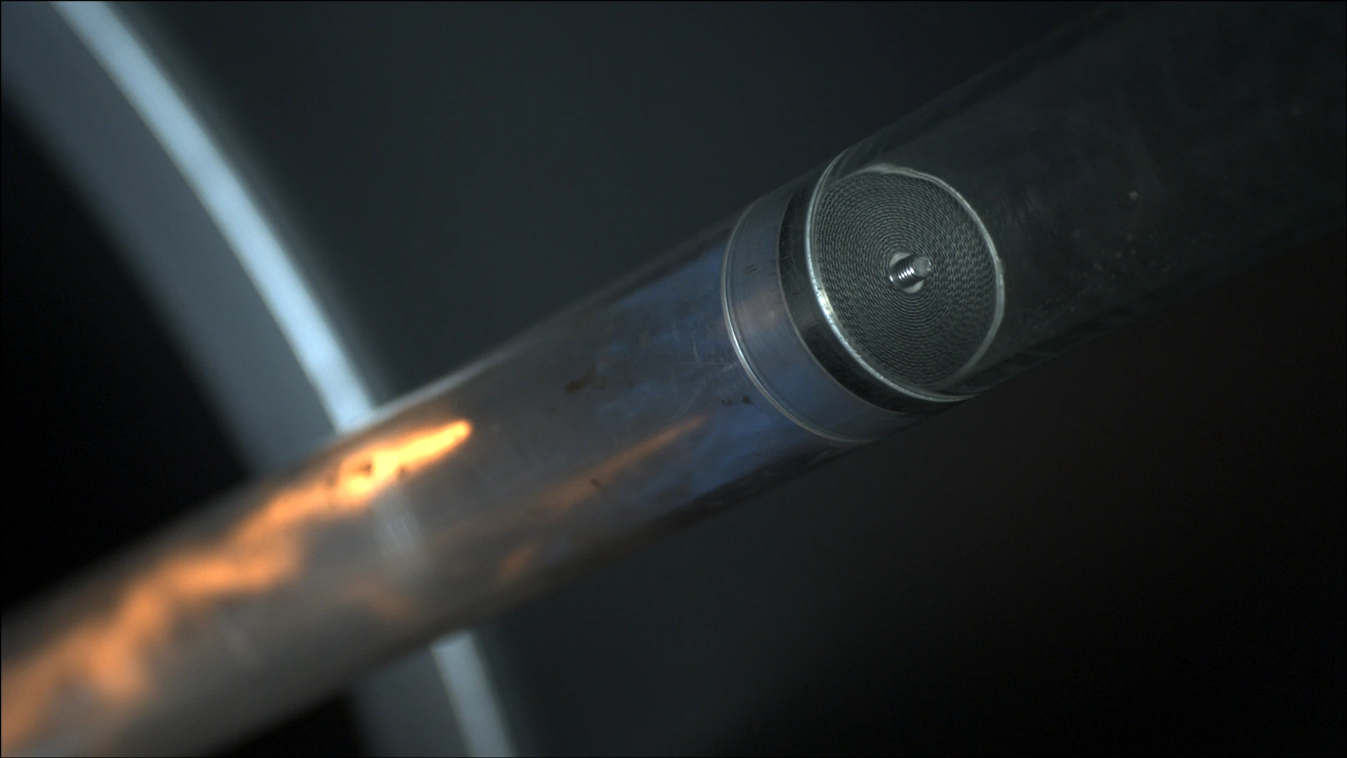
Main Component – PROTEGO® Flame Arrester Unit

For Explosion Group IIA
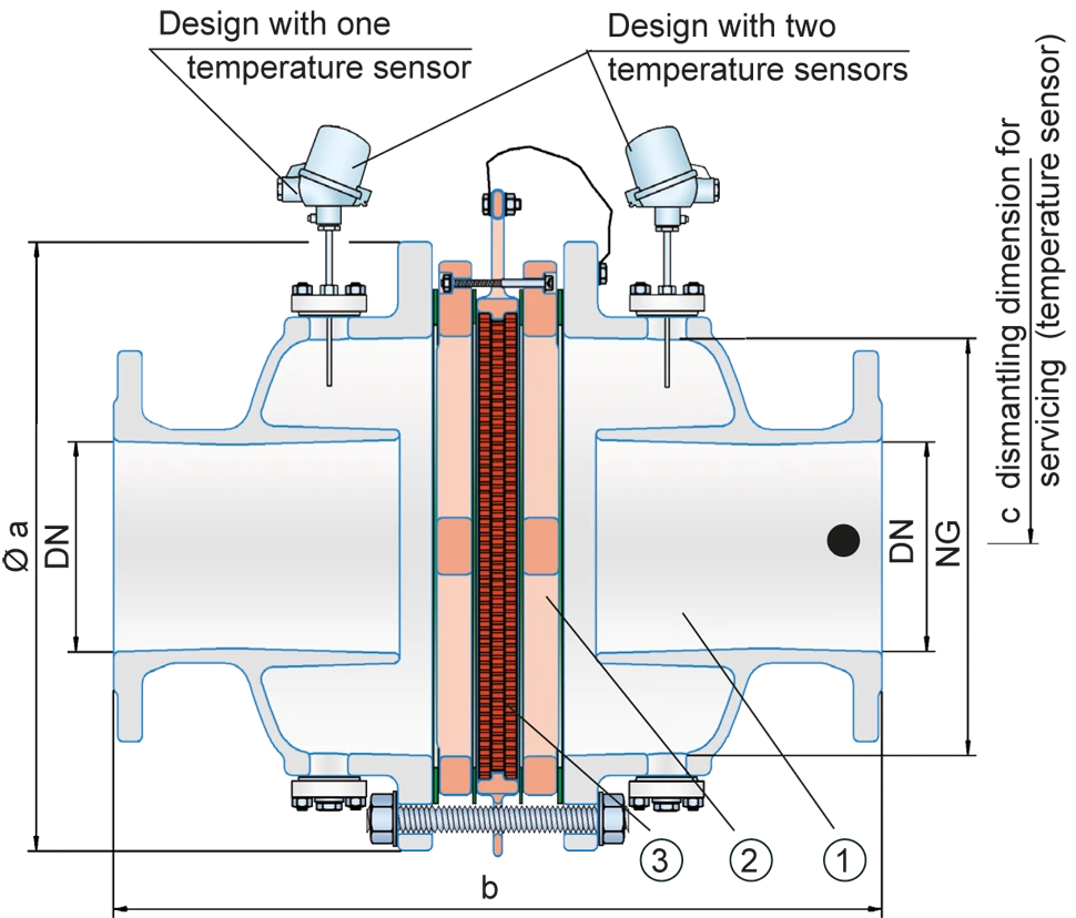
Dimensions
To select series and nominal size (DN) - nominal width (NG) combination, please use the flow capacity chart on the following page
| DN | 50 / 2" | 80 / 3" | 100 / 4" | 150 / 6" |
| NG | 150 / 6" | 150 / 6" | 200 / 8" | 300 / 12" |
| a | 287 / 11.30 | 287 / 11.30 | 342 / 13.46 | 447 / 17.60 |
| b | 380 / 14.96 | 380 / 14.96 | 468 / 18.43 | 612 / 24.09 |
| c | 430 / 16.93 | 430 / 16.93 | 480 / 18.90 | 530 / 20.87 |
Dimensions in mm / inches
Selection of explosion group
| MESG | Expl. Gr. (IEC / CEN) | Gas Group (NEC) |
| > 0.90 mm | IIA | D |
Special approvals upon request
Selection of max. operating pressure
| DN | 50 / 2" | 80 / 3" | 100 / 4" | 150 / 6" |
| NG | 150 / 6" | 150 / 6" | 200 / 8" | 300 / 12" |
| Pmax | 1.6 / 23.2 | 1.6 / 23.3 | 1.2 / 17.4 | 1.2 / 17.4 |
Pmax = in bar / psi absolut, higher operating pressure upon request
Specification of max. operating temperature
| ≤ 60°C / 140°F | Tmaximum allowable operating temperature in °C |
| - | Designation |
higher operating temperatures upon request
Material for housing
| Design | A |
| Housing | Steel with an ECTFE coating |
| Gasket | PTFE |
| Flame arrester unit Flame arrester unit Flame arrester casing with FLAMEFILTER® set. | A, B, C |
Special materials upon request
Material combinations of flame arrester unit
| Design | A | B | C |
| FLAMEFILTER® cage | Steel with an ECTFE coating | Hastelloy | Stainless Steel |
| Spider rings | Steel with an ECTFE coating | Hastelloy | Stainless Steel |
| FLAMEFILTER®* | PTFE* | PTFE* | PTFE* |
| Spacer Spacer The spacer is a component that is generally used in a PROTEGO® flame arrester as a spacer within the FLAMEFILTER® se | PEEK / ETFE / FEP | PEEK / ETFE / FEP | PEEK / ETFE / FEP |
* electrically conductive
Special materials upon request.
Flange connection type
| EN 1092-1; Form B1 |
| ASME B16.5 CL 150 R.F. |
other connections upon request
Flow Capacity Chart
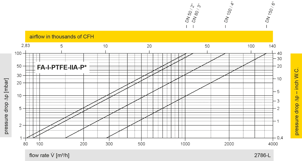
The flow capacity charts have been determined with a calibrated and TÜV certified flow capacity test rig. Volume flow V in (m³/h) and CFH refer to the standard reference conditions of air ISO 6358 (20°C, 1bar). For conversion to other densities and temperatures refer to Sec. 1: “Technical Fundamentals”.


Contact CSR Department
