Features

Virtually Maintenance-Free
Low Costs
low operating and lifecycle costs
Function and Description

Ent- und Belüftung - Verhindert das Eindringen von Wasser und Schmutz

The PROTEGO® E/H0 vent cap Vent cap End-of-line device for free out-breathing and in-breathing of plant components. This device can be flame transmission-proof. allows vessels which are not pressurized to vent. This device Device A device is a pipe component that influences the media flow by opening, closing, or partially shutting off the flow channel or by dividing or mixing the media flow. prevents rain and dirt from entering the vent line. The EH/0 vent cap is not flame transmission proof. It is often used in combination with detonation flame arresters Detonation flame arrester Flame arrester designed to prevent the transmission of a detonation. , when those are used in vent lines, installed at a position which creates a long run up distance from the end of the vent line to prevent endurance burning Endurance burning Stabilized burning for an unlimited time. . The PROTEGO® EH/0 vent cap will then be installed at the end of that vent line to prevent particles or rain from entering the line.

Weather Protection Hood for Preventing Foreign Object Ingress and Animal Nesting
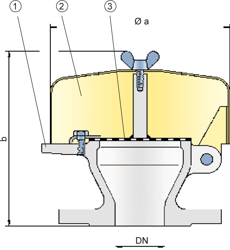
The vent cap PROTEGO® EH/0 main components are a housing Housing A housing is a solid shell, which surrounds a content, either protecting the content from external influences, or protecting the environment from the content. (1), a weather hood (2) and a protection screen (3). The device is equipped with a fixed weather hood out of metal. The protection screen prevents particles or rain from entering the animals.

Dimensions

To select the nominal size Nominal size The nominal size is an alphanumeric designation of size for components in a piping system, used for reference purposes, comprising the letters DN followed by a dimensionless integer that is indirectly related to the physical size of the bore or outside diameter of the connections, expessed in millimeters. (DN), please use the flow capacity charts on the following pages

DN20 / ¾" 25 / 1" 32 / 1¼" 40 / 1½"50 / 2" 65 / 2½" 80 / 3"
a163 / 6.42163 / 6.42163 / 6.42183 / 7.20183 / 7.20218 / 8.58218 / 8.58
b175 / 6.89175 / 6.89175 / 6.89190 / 7.48190 / 7.48200 / 7.87200 / 7.87

Dimensions in mm / inches

Material selection

Design AB
HousingSteelStainless Steel
Weather hoodSteelStainless Steel

Special materials upon request

Flange connection type

EN 1092-1; Form B1
ASME B16.5 CL 150 R.F.

other types upon request

Design Types and Specifications

Following designs are available:
Vent cap, basic designEH/0

Special designs available on request

Flow Capacity Chart

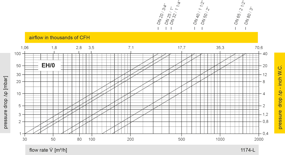
The flow capacity charts have been determined with a calibrated and TÜV certified flow capacity test rig. Volume flow V in (m³/h) and CFH refer to the standard reference conditions of air ISO 6358 (20°C, 1bar). For conversion to other densities and temperatures refer to Sec. 1: “Technical Fundamentals”.

Applications

Contact CSR Department 

If you have any questions, feedback, or additional input, our team of experts will be glad to support you.

Picture of Mrs. Auris-Nadine Hillen
Mrs. Auris-Nadine Hillen

CSR Department

+49 (0)5307 809 108