Features
Large Diaphragm Area
Stainless Steel or Hastelloy
Simple Adjustment of Set Pressure
Any Installation Position
Exteral Energy Supply
High Flow Capacity
Guided Valve Pallet
Precision
Used in Explosion Hazardous Areas
Sturdy Housing Design
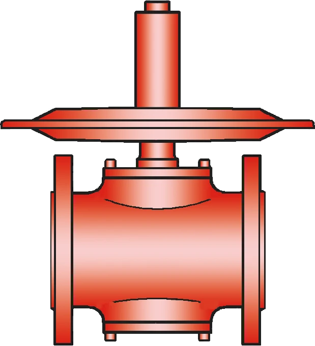
Highly Developed Low-Pressure Reducing Valve
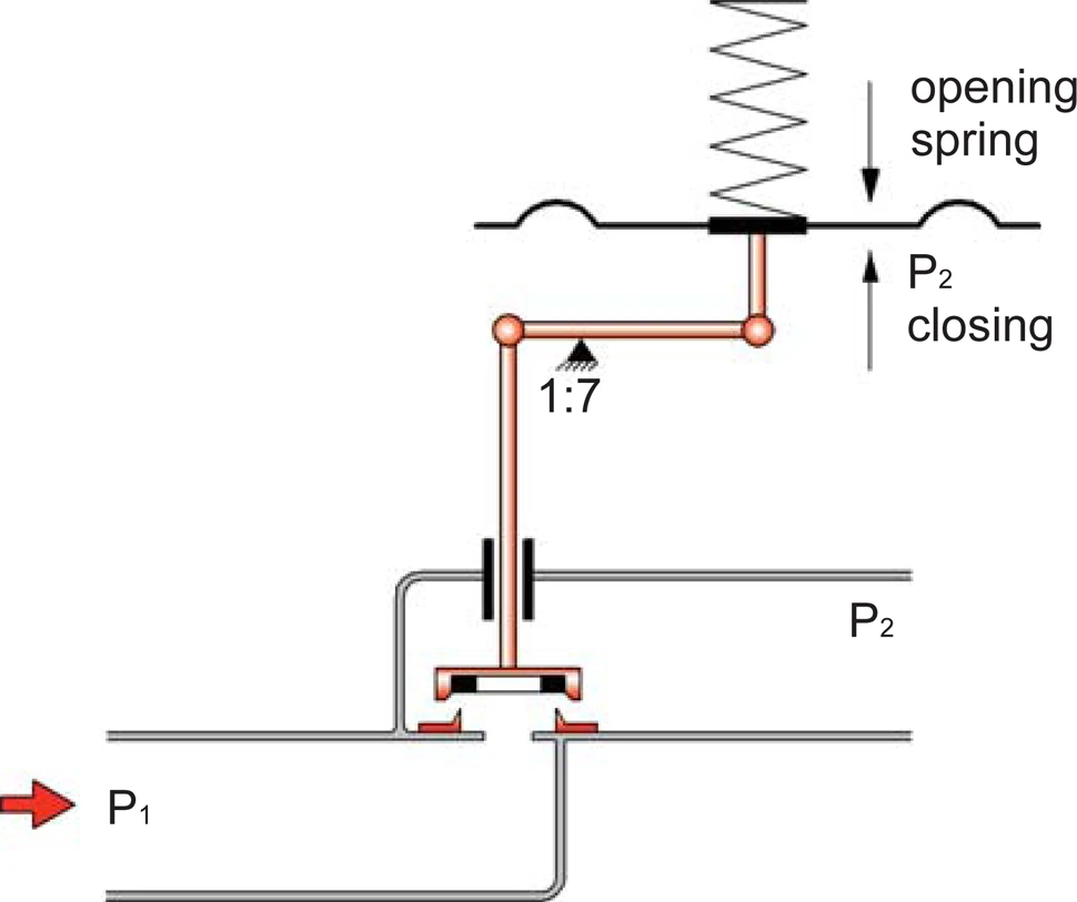
Membrane-Controlled and Spring-Loaded Proportional Regulator
For Precise Pressure Control
Precise Pressure Control up to -200 mbar
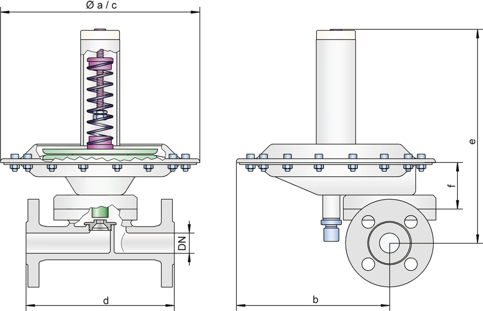
Dimensions
To select the nominal size Nominal size The nominal size is an alphanumeric designation of size for components in a piping system, used for reference purposes, comprising the letters DN followed by a dimensionless integer that is indirectly related to the physical size of the bore or outside diameter of the connections, expessed in millimeters. (DN), please use the flow capacity charts on the following pages
| DN | 15 / ½" | 25 / 1'' | 50 / 2'' | 100 / 4'' | 15 / ½" | 25 / 1'' | 50 / 2'' | 100 / 4'' | |
| a | 214 | 214 | – | – | 8.43 | 8.43 | – | – | |
| b | 168 | 168 | – | – | 6.61 | 6.61 | – | – | |
| c* | – | – | 214 / 360 | 360 / 600 | – | – | 8.43 / 14.17 | 14.17 / 23.62 | |
| d | DIN | 150 | 160 | 150 | 250 / 250 | 5.91 | 6.3 | 5.91 | 9.84 / 9.84 |
| ANSI | 180 | 160 | 150 | 250 / 250 | 7.09 | 6.3 | 5.91 | 9.84 / 9.84 | |
| e | 214 | 214 | 230 | 275 / 310 | 8.43 | 8.43 | 9.06 | 10.83 / 12.2 | |
| f | 87 | 87 | 103 | 148 / 155 | 3.43 | 3.43 | 4.06 | 5.83 / 6.10 |
Dimensions in mm / inches
*depends upon size of diaphragm
Dimensions
Selection of valve seat Valve seat The valve seat is a component on which the valve pallet rests when the valve is closed. depending on flow rate
| Size | Seat in mm / inches | Kvs | Number |
| 25 / 1'' | 2,0 / 0.08 | 0,15 | 20 |
| 4,5 / 0.18 | 0,60 | 45 | |
| 7,5 / 0.30 | 1,20 | 75 | |
| 10,0 / 0.39 | 1,70 | 100 | |
| 14,0 / 0.55 | 2,40 | 140 | |
| 50 / 2'' | 14,0 / 0.55 | 2,80 | 140 |
| 18,0 / 0.71 | 6,80 | 180 | |
| 26,0 / 1.02 | 14,50 | 260 | |
| 100 / 4'' | 42,0 / 1.65 | 33,50 | 420 |
| 55,0 / 2.17 | 68,00 | 550 |
*1 Kvs = 0.86 Cv; 1 Cv = 1.17 Kvs
Material selection for housing
| Design | S | H | |
| Housing Housing A housing is a solid shell, which surrounds a content, either protecting the content from external influences, or protecting the environment from the content. | Stainless Steel | Hastelloy | |
| Valve seat | Stainless Steel | Hastelloy | |
| Valve pallet | Stainless Steel | Hastelloy | |
| Valve seat sealing | FFKM | FFKM | |
| Gasket | PTFE | PTFE | |
| Diaphragm P | PTFE | PTFE | Marking P |
| Alternative: Diaphragm V | Viton | - | Marking V |
Optional: Inner part of housing electropolished. Special materials upon request
Type of connection
| FD | DIN 2501, PN 16 | DIN |
| FA | ASME B16.5 CL 150 R.F. | ASME |
| G | Thread | G or NPT |
other types upon request
Flow rates for P2 pressure range (Europe - metric units)
ZM-R 15 / ZM-R 25: flow rate (air, 0°C) at ∆P = P1 - P2 and valve full open
| P 1 (bar) | 0,15 | 0,25 | 0,40 | 0,65 | 1,00 | 1,50 | 2,50 | 4,00 | 6,00 | 10,00 | Sitz-Ø |
| P 2 (mbar) | [Nm³ / h] | [Nm³ / h] | [Nm³ / h] | [Nm³ / h] | [Nm³ / h] | [Nm³ / h] | [Nm³ / h] | [Nm³ / h] | [Nm³ / h] | [Nm³ / h] | [mm] |
| 10 | 6,2 12,4 17,5 24,8 | 8,1 16,2 23,0 32,5 | 10,3 20,7 29,3 41,4 | 13,2 26,5 37,6 53,1 | 16,5 33,0 46,7 66,0 | 20,6 41,2 58,4 82,4 | 28,8 57,6 81,6 115,2 | 41,1 82,2 116,5 164,5 | 57,5 115,0 163,0 230,1 | 90,3 180,7 256,0 361,4 | Ø4,5 Ø7,5 Ø10,0 Ø14,0 |
| 20 | 6,0 12,0 17,0 24,0 | 7,9 15,9 22,6 31,9 | 10,2 20,5 29,1 41,1 | 13,2 26,4 37,5 52,9 | 16,5 33,0 46,7 66,0 | 20,6 41,2 58,4 82,4 | 28,8 57,6 81,6 115,2 | 41,1 82,2 116,5 164,5 | 57,5 115,0 163,0 230,1 | 90,3 180,7 256,0 361,4 | Ø4,5 Ø7,5 Ø10,0 Ø14,0 |
| 100 | 3,8 7,7 10,9 15,4 | 6,7 13,4 18,9 26,8 | 9,4 18,9 26,8 37,9 | 12,8 25,6 36,3 51,3 | 16,4 32,8 46,5 65,6 | 20,6 41,2 58,4 82,4 | 28,8 57,6 81,6 115,2 | 41,1 82,2 116,5 164,5 | 57,5 115,0 163,0 230,1 | 90,3 180,7 256,0 361,4 | Ø4,5 Ø7,5 Ø10,0 Ø14,0 |
| 200 | - - - - | 4,0 8,0 11,4 16,1 | 8,00 16,1 22,9 32,3 | 12,1 24,2 34,3 48,4 | 16,1 32,3 45,8 64,6 | 20,6 41,2 58,4 82,4 | 28,8 57,6 81,6 115,2 | 41,1 82,2 116,5 164,5 | 57,5 115,0 163,0 230,1 | 90,3 180,7 256,0 361,4 | Ø4,5 Ø7,5 Ø10,0 Ø14,0 |
| 500 | - - - - | - - - - | - - - - | 7,8 15,6 22,1 31,2 | 14,2 28,5 40,4 57,0 | 20,1 40,3 57,1 80,7 | 28,8 57,6 81,6 115,2 | 41,1 82,2 116,5 164,5 | 57,5 115,0 163,0 230,1 | 90,3 180,7 256,0 361,4 | Ø4,5 Ø7,5 Ø10,0 Ø14,0 |
Flow rates for P2 pressure range (Europe - metric units)
ZM-R 50: flow rate (air, 0°C) at ∆P = P1 - P2 and valve full open
| P 1 (bar) | 0,15 | 0,25 | 0,40 | 0,65 | 1,00 | 1,50 | 2,50 | 4,00 | 6,00 | 10,00 | Sitz-Ø |
| P 2 (bar) | [Nm³ / h] | [Nm³ / h] | [Nm³ / h] | [Nm³ / h] | [Nm³ / h] | [Nm³ / h] | [Nm³ / h] | [Nm³ / h] | [Nm³ / h] | [Nm³ / h] | [mm] |
| 10 | 28,9 70,3 150,0 | 37,9 92,1 196,5 | 48,3 117,4 250,4 | 61,9 150,4 320,8 | 77,0 187,1 399,1 | 96,2 233,6 498,3 | 134,5 326,6 696,5 | 191,9 466,1 994,0 | 268,5 652,1 1390 | 421,6 1024 2183 | Ø14,0 Ø18,0 Ø26,0 |
| 20 | 28,0 68,1 145,3 | 37,3 90,6 193,3 | 47,9 116,5 248,4 | 61,7 150,0 319,9 | 77,0 187,1 399,0 | 96,2 233,6 498,3 | 134,5 326,6 696,5 | 191,9 466,1 994,0 | 268,5 652,1 1390 | 421,6 1024 2183 | Ø14,0 Ø18,0 Ø26,0 |
| 100 | 18,0 43,8 93,5 | 31,2 75,9 162,0 | 44,2 107,4 229,1 | 59,9 145,5 310,2 | 76,6 186,1 396,9 | 96,2 233,6 498,3 | 134,5 326,6 696,5 | 191,9 466,1 994,0 | 268,5 652,1 1390 | 421,6 1024 2183 | Ø14,0 Ø18,0 Ø26,0 |
| 200 | - - - | 18,8 45,8 97,6 | 37,7 91,6 195,3 | 56,5 137,4 293,0 | 75,4 183,2 390,6 | 96,2 233,6 498,3 | 134,5 326,6 696,5 | 191,9 466,1 994,0 | 268,5 652,1 1390 | 421,6 1024 2183 | Ø14,0 Ø18,0 Ø26,0 |
| 500 | - - - | - - - | - - - | 36,4 88,6 188,9 | 66,6 161,7 344,9 | 94,1 228,7 487,8 | 134,5 326,6 696,5 | 191,9 466,1 994,0 | 268,5 652,1 1390 | 421,6 1024 2183 | Ø14,0 Ø18,0 Ø26,0 |
Flow rates for P2 pressure range (Europe - metric units)
ZM-R 100: flow rate (air, 0°C) at ∆P = P1 - P2 and valve full open
| P 1 (bar) | 0,15 | 0,25 | 0,40 | 0,65 | 1,00 | 1,50 | 2,50 | 4,00 | 6,00 | 10,00 | Sitz-Ø |
| P 2 (bar) | [Nm³ / h] | [Nm³ / h] | [Nm³ / h] | [Nm³ / h] | [Nm³ / h] | [Nm³ / h] | [Nm³ / h] | [Nm³ / h] | [Nm³ / h] | [Nm³ / h] | [mm] |
| 10 | 346 703 | 453 921 | 587 1174 | 741 1504 | 922 1871 | 1151 2336 | 1609 3266 | 2296 4661 | 3212 6512 | 5045 10241 | Ø42,0 Ø55,0 |
| 20 | 335 681 | 446 906 | 574 1165 | 739 1500 | 921 1871 | 1151 2336 | 1609 3266 | 2296 4661 | 3212 6512 | 5045 10241 | Ø42,0 Ø55,0 |
| 100 | 216 438 | 374 759 | 529 1074 | 716 1455 | 917 1861 | 1151 2336 | 1609 3266 | 2296 4661 | 3212 6512 | 5045 10241 | Ø42,0 Ø55,0 |
| 200 | - - | 225 458 | 451 916 | 676 1374 | 902 1832 | 1151 2336 | 1609 3266 | 2296 4661 | 3212 6512 | 5045 10241 | Ø42,0 Ø55,0 |
| 500 | - - | - - | - - | 436 886 | 796 1617 | 1127 2287 | 1609 3266 | 2296 4661 | 3212 6512 | 5045 10241 | Ø42,0 Ø55,0 |
Flow rates for P2 vacuum range (Type ZM-R/N) upon request


Contact CSR Department
