LDA
Liquid Detonation Flame Arrester for filling lines - internal installation
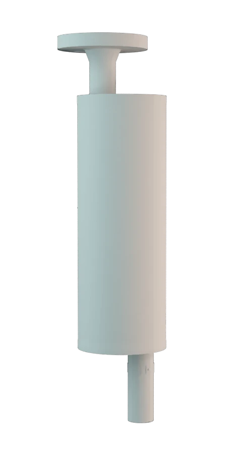
Features
Low Risk
Meets TRGS Requirements
Different Connections
Explosion Safety
For Flammable Liquids
Low Pressure Loss
Prevention of Flame Spread in Tank During Ignition
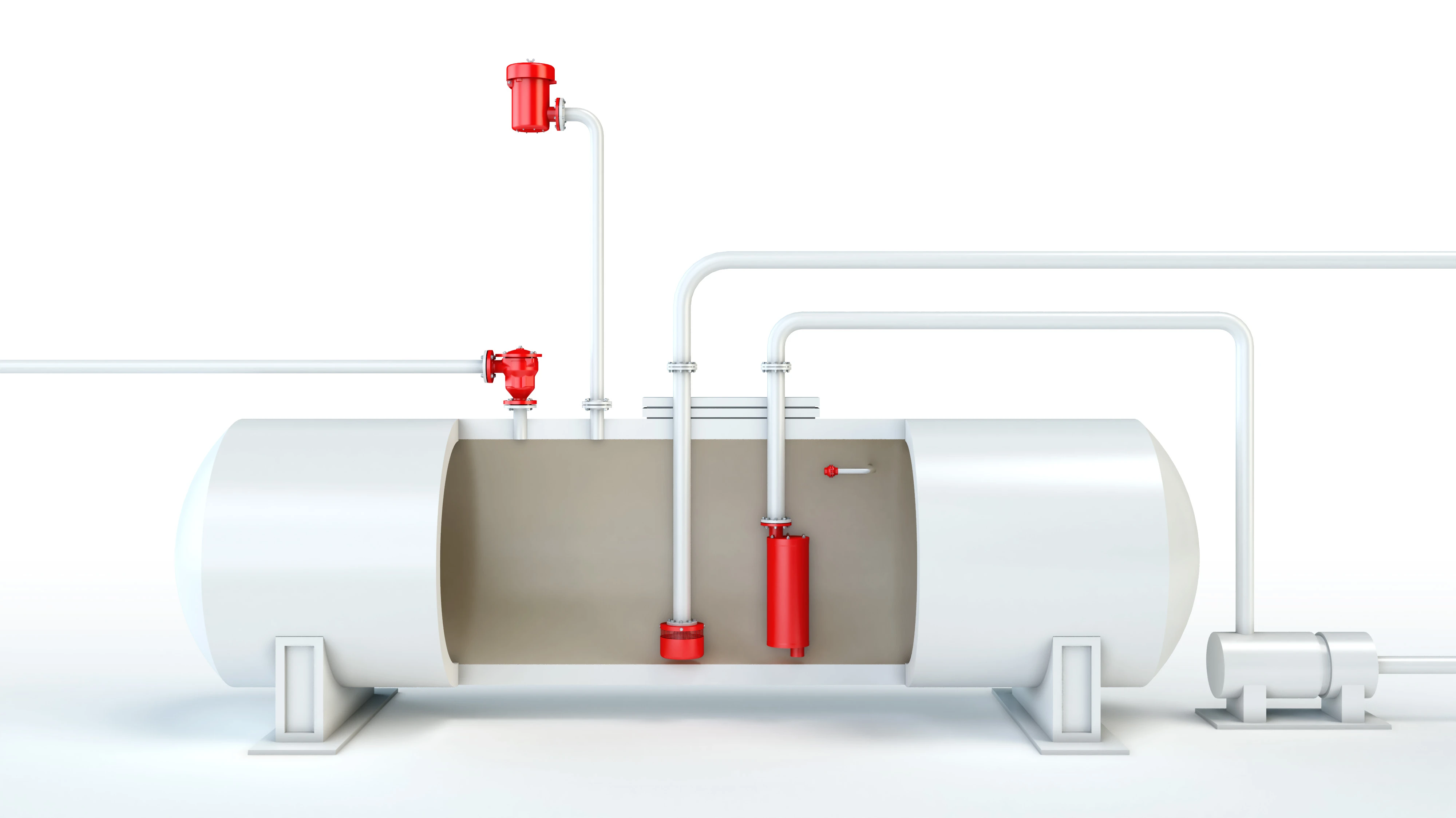
Reduction of Flame Propagation Speed

For Explosion Groups IIA to IIB3
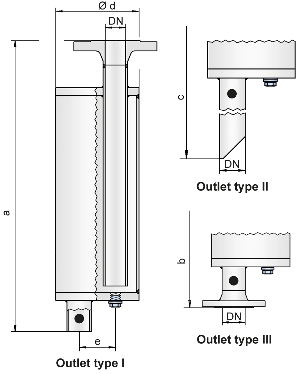
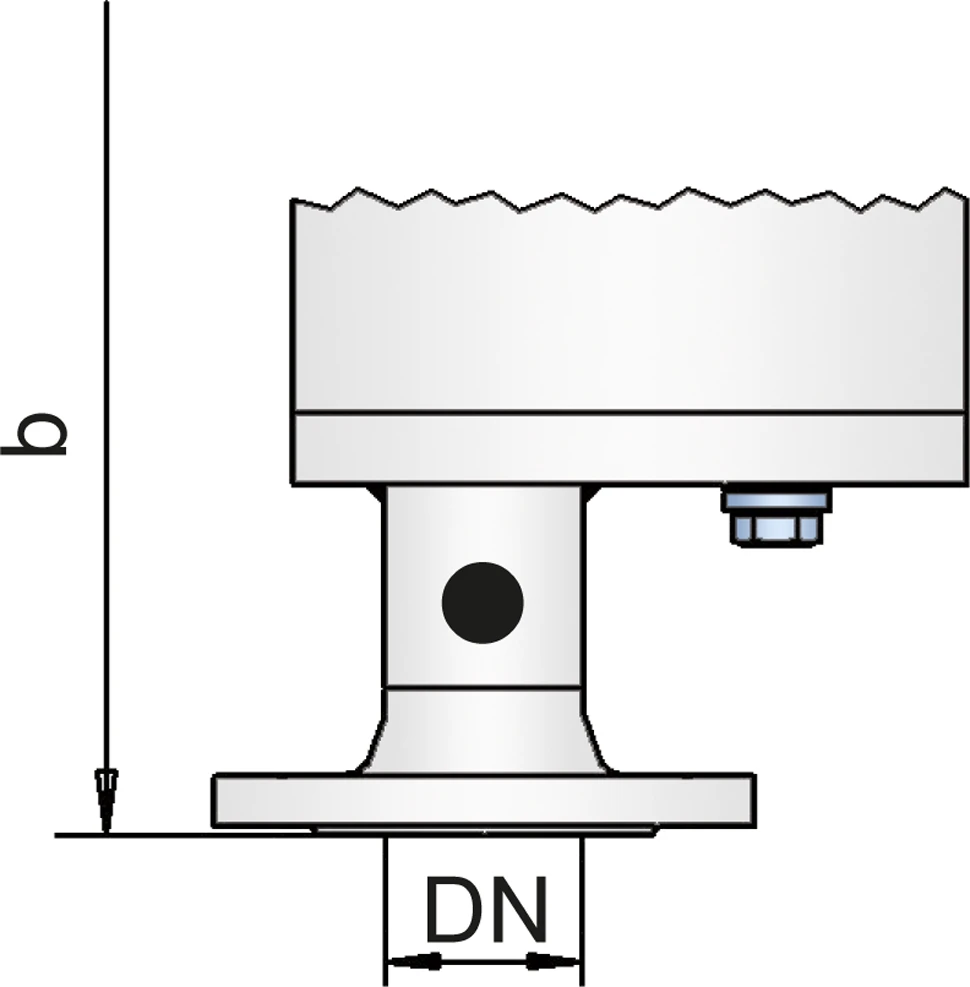
Dimensions
To select the nominal size Nominal size The nominal size is an alphanumeric designation of size for components in a piping system, used for reference purposes, comprising the letters DN followed by a dimensionless integer that is indirectly related to the physical size of the bore or outside diameter of the connections, expessed in millimeters. (DN), please use the flow capacity chart on the following pages
| DN | 25 / 1" | 32 / 1¼“ | 40 / 1½“ | 50 / 2" | 65 / 2½“ | 80 / 3" | 100 / 4" | 125 / 5" | 150 / 6" | 200 / 8" | 250 / 10" |
| a | 500 / 19.69 | 580 / 22.83 | 700 / 27.56 | 700 / 27.56 | 825 / 32.48 | 925 / 36.42 | 1050 / 41.34 | 1150 / 45.28 | 1350 / 53.15 | 1650 / 64.96 | 2000 / 78.74 |
| b | 538 / 21.18 | 620 / 24.41 | 745 / 29.33 | 745 / 29.33 | 870 / 34.25 | 975 / 38.39 | 1102 / 43.39 | 1205 / 47.44 | 1405 / 55.31 | 1712 / 67.40 | 2068 / 81.42 |
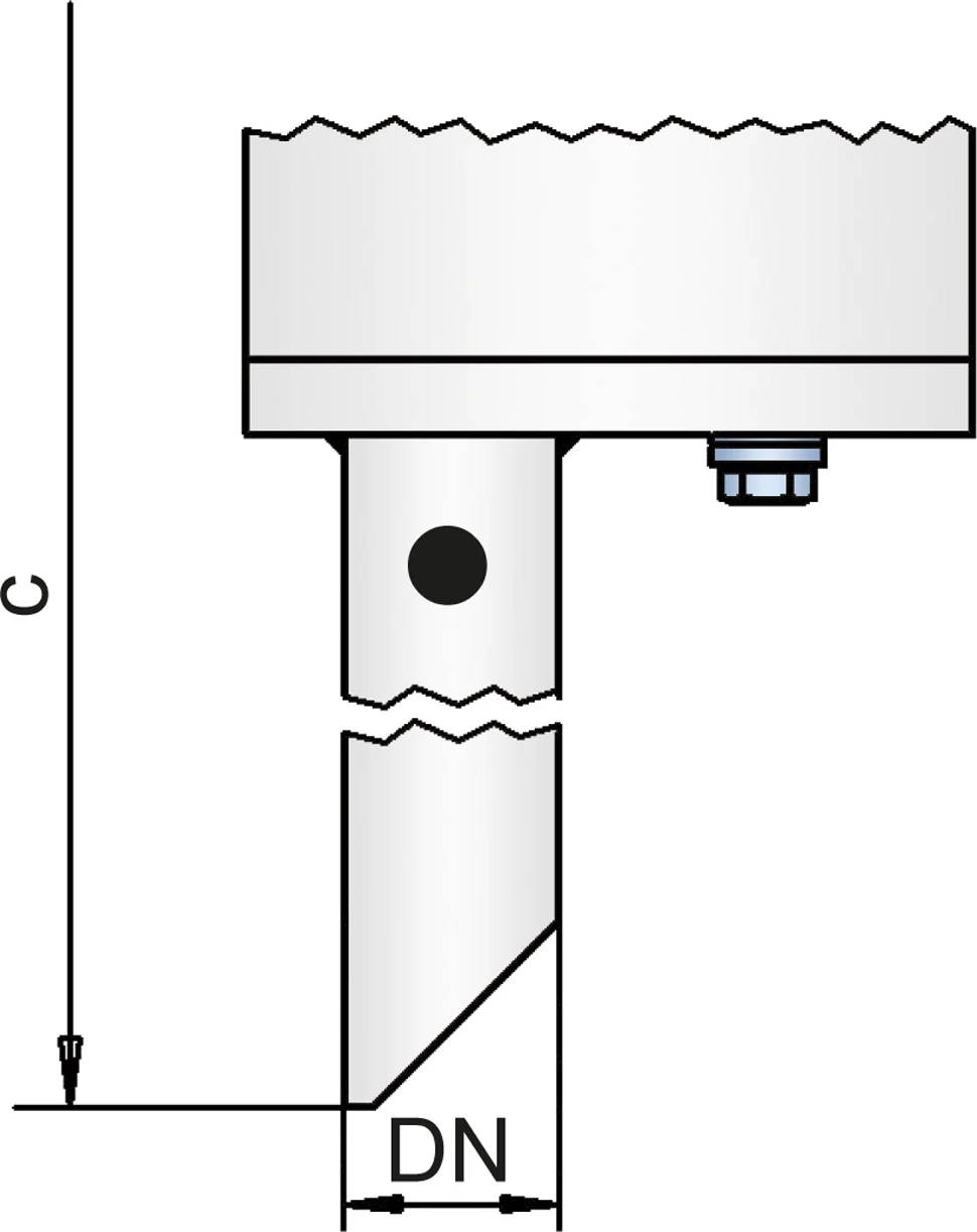
| c | 725 / 28.54 | 805 / 31.69 | 925 / 36.42 | 925 / 36.42 | 1050 / 41.34 | 1145 / 45.08 | 1270 / 50.00 | 1380 / 54.33 | 1580 / 62.20 | 1880 / 74.02 | 2300 / 90.55 |
| d | 115 / 4.53 | 140 / 5.51 | 168 / 6.61 | 168 / 6.61 | 220 / 8.66 | 245 / 9.65 | 325 / 12.80 | 356 / 14.02 | 500 / 19.69 | 600 / 23.62 | 700 / 27.56 |
| e | 50 / 1.97 | 58 / 2.28 | 65 / 2.56 | 65 / 2.56 | 95 / 3.74 | 105 / 4.13 | 135 / 5.31 | 155 / 6.10 | 200 / 7.87 | 250 / 9.84 | 300 / 11.81 |
Dimensions in mm / inches
Selection of explosion group
| MESG | Expl. Gr. (IEC / CEN) | Gas Group (NEC) |
| > 0,90 mm | IIA | D |
| ≥ 0,65 mm | IIB3 | C |
Special approvals upon request
Specification of max. operating temperature
| ≤ 60°C / 140°F | Tmaximum allowable operating temperature Operating temperature Temperature reached when the equipment is operating under design conditions. in °C |
| - | Designation |
higher operating temperatures upon request
Material selection for housing
| Design | A | B |
| Housing Housing A housing is a solid shell, which surrounds a content, either protecting the content from external influences, or protecting the environment from the content. | Steel | Stainless Steel |
| Gasket | PTFE | PTFE |
Special materials upon request
Flange connection type
| EN 1092-1; Form B1 |
| ASME B16.5 CL 150 R.F. |
other types upon request
Outlet type
| Straight pipe | I |
| Beveled pipe | II |
| EN 1092-1, Form B1 or DIN 2501, Form C | III (EN or DIN) |
| ASME B16.5 CL 150 R.F. | III (ASME) |
other types upon request
Flow Capacity Chart
The volume flow V in m³/h was determined with water according to DIN EN 60534 at a temperature Tn = 20°C and an atmospheric pressure pn = 1,013 bar, kinematic viscosity v = 10-6 m²/s
To avoid electrostatic charge of flammable liquids the maximum flow is limited (refer to TRGS 727, CENELEC-Report CLC/TR 60079-32-1).


Contact CSR Department
