
Features
Comprehensive Weather Protection
Weather Hood With Protection Screen Protects the PROTEGO® Flame Arrester Unit Against Environmental Impact, Such as Nesting Animals and Weather Conditions
Easy Maintenance
Without Disassembling of the FLAMEFILTER®
Fastest Disassembly and Assembly
of Single FLAMEFILTER®
Pipe Thread Connection
Saftey
Provides Protection Against Atmospheric Deflagrations, Short-Time Burning
Low Costs
Low Operating and Lifecycle Costs
Spare Parts
Cost-Effective Spare Parts
Function and Description
Protection Against Atmospheric Deflagrations
The
Pressure/vacuum relief valve
Pressure/vacuum relief valve is an umbrella term that includes pressure or vacuum relief valve as well as pressure and vacuum relief valve.
PROTEGO® BE/AD End-of-Line
Deflagration Flame Arrester
Deflagration flame arrester
Flame arrester designed to prevent the transmission of a deflagration. It can be an end-of-line flame arrester or an in-line flame arrester.
provides protection against atmospheric deflagrations. The
device
Device
A device is a pipe component that influences the media flow by opening, closing, or partially shutting off the flow channel or by dividing or mixing the media flow.
is usually installed on vent lines of small vessels and plant
equipment
Equipment
Machines, appliances, fixed or mobile devices, control parts and accessories, and warning and prevention systems, whether separate or combined, intended for the generation, transfer, storage, measurement, control, and conversion of energy, and for the processing of materials, which have their own potential source of ignition and may cause an explosion.
which are not pressurized. For safe application, it is important that an
endurance burning
Endurance burning
Stabilized burning for an unlimited time.
situation can be excluded. So typically, it is installed on vents lines which discharge vapor for a short time period. The device is the ideal solution for preventing flame transmission from atmospheric
deflagration
Deflagration
Explosion propagating at subsonic velocity (EN 1127-1:1997).
into the
vessel
Vessel
Container or structural envelope in which materials are processed, treated or stored.
or plant.

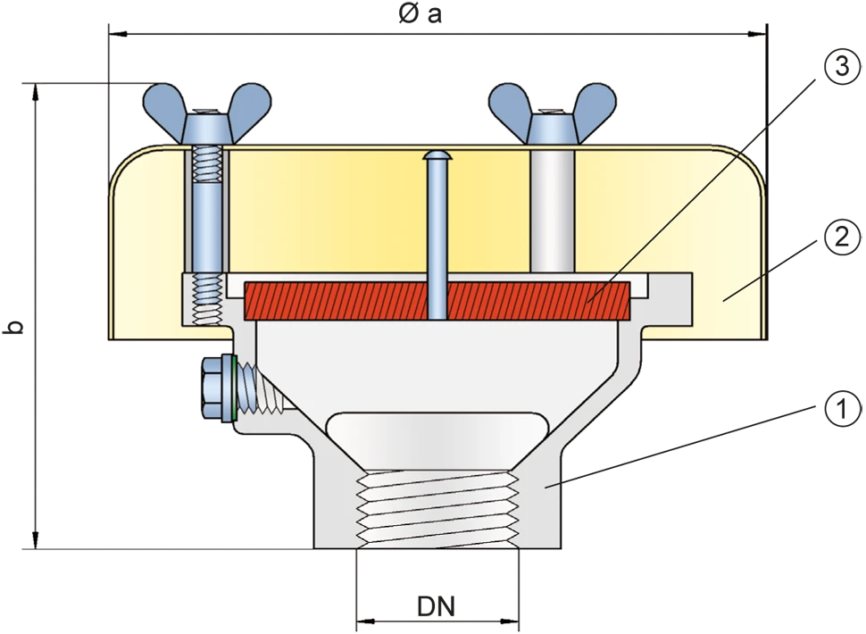
Main Component – PROTEGO® Flame Arrester Unit
The PROTEGO® BE/AD consists of the
housing
Housing
A housing is a solid shell, which surrounds a content, either protecting the content from external influences, or protecting the environment from the content.
(1), a
weather hood
Weather hood
A weather hood is a cover to protect the internal components of a device from environmental influences.
(2), and the PROTEGO® Flame Arrester Unit (3). The device is equipped with a metal weather hood. The FLAMEFILTER® gap size will depend on the device’s intended use.

For Explosion Groups IIA to IIC
Specifying the operating conditions, such as the temperature, pressure,
explosion
Explosion
Abrupt oxidation or decomposition reaction producing an increase in temperature, pressure, or in both simultaneously.
group, and the composition of the fluid, enables PROTEGO® to select the best End-of-Line Deflagration Flame Arrester for your application. The PROTEGO® BE/AD Series End-of-Line Deflagration Flame Arrester is available for substances from explosion groups IIA to IIC (NEC groups D to B).
The standard design can be used with an
operating temperature
Operating temperature
Temperature reached when the equipment is operating under design conditions.
of up to +60°C / 140°F.
EU conformity according to the currently valid ATEX directive. Approvals according to other national/international regulations on request.
Product Data
Dimensions
| DN | 15 / G ½" | 20 / G ¾" | 25 / G 1" | 32 / G 1¼" | 40 / G 1½" | 50 / G 2" |
| a | 116 / 4.57 | 116 / 4.57 | 116 / 4.57 | 116 / 4.57 | 200 / 7.87 | 200 / 7.87 |
| b | 80 / 3.15 | 80 / 3.15 | 85 / 3.35 | 85 / 3.35 | 150 / 5.91 | 150 / 5.91 |
Dimensions in mm / inches
Selection of explosion group
| MESG | Expl. Gr. (IEC / CEN) | Gas Group (NEC) |
| ≥ 0,65 mm | IIB3 | C |
| < 0,5 mm | IIC | B |
Special approvals upon request
Specification of max. operating temperature
| ≤ 60°C / 140°F | Tmaximum allowable operating temperature in °C |
| - | Designation |
higher operating temperatures upon request
Material selection
| Design | B | C | |
| Housing | Steel | Stainless Steel | Hastelloy |
| Weather Hood | Stainless Steel | Stainless Steel | Stainless Steel |
| FLAMEFILTER® | Stainless Steel | Stainless Steel | Hastelloy |
Special materials upon request
Type of connection
| Pipe thread DIN ISO 228-1 | DIN |
other types of thread upon request
Flow Capacity Chart
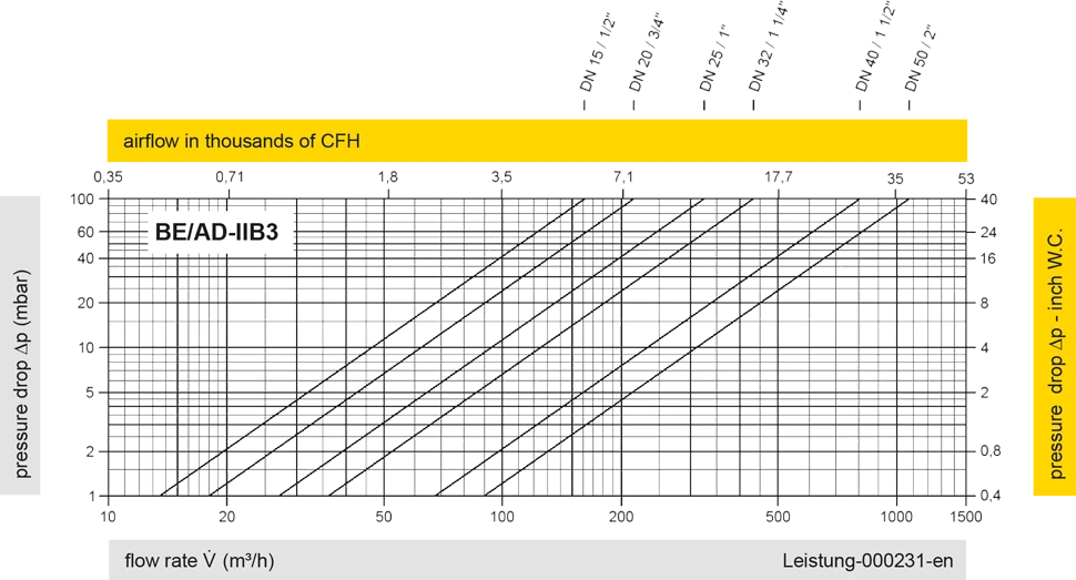
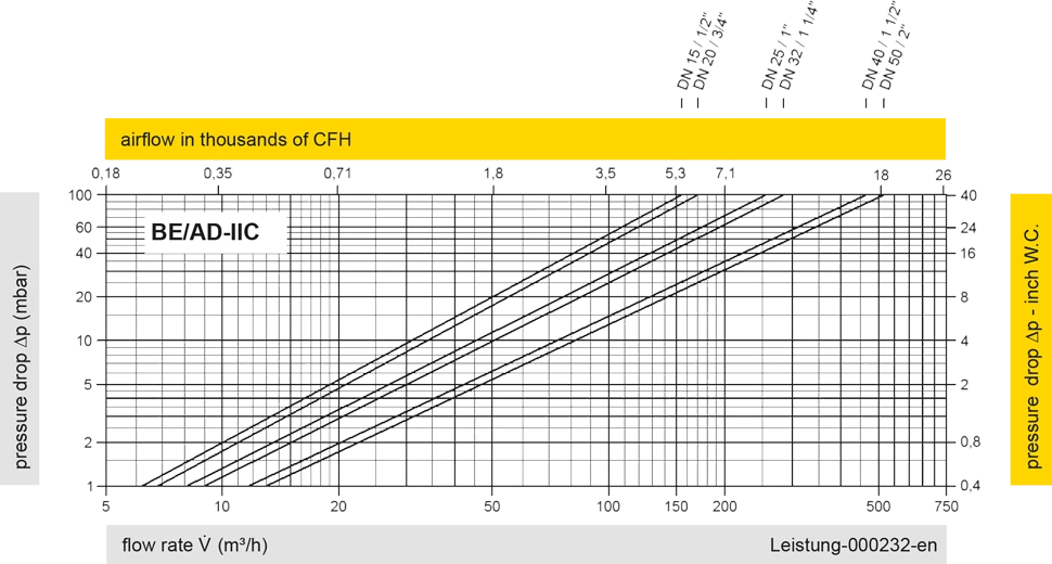
The flow capacity charts have been determined with a calibrated and TÜV certified flow capacity test rig. Volume flow V in (m³/h) and CFH refer to the standard reference conditions of air ISO 6358 (20°C, 1bar). For conversion to other densities and temperatures refer to Sec. 1: “Technical Fundamentals”.


Contact CSR Department
