DA-CG
In-Line Detonation Flame Arrester for unstable and stable detonations and deflagrations in a straight through design with shock absorber, bidirectional
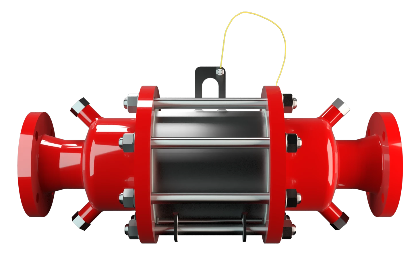
Features
Explosion Safety
Reduced Number of FLAMEFILTER® Discs
Modular Design
Differnt Series
Easy Maintenance
Large Sizes
Extended Application Range
Bi-Directional Flame Transmission
Temperature Sensors Possible
Spare Parts
Low Costs
Requirements of the US Coast Guard

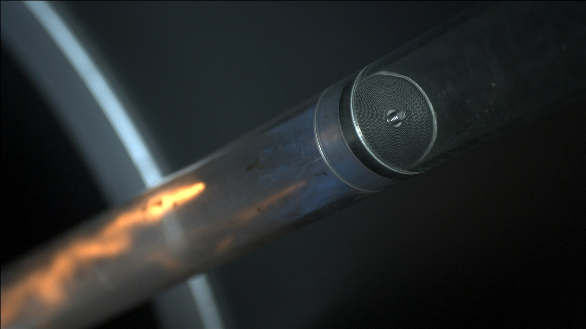
Main Component – PROTEGO® Flame Arrester Unit
For Explosion Groups IIA to IIB3

Many Individual Certifications
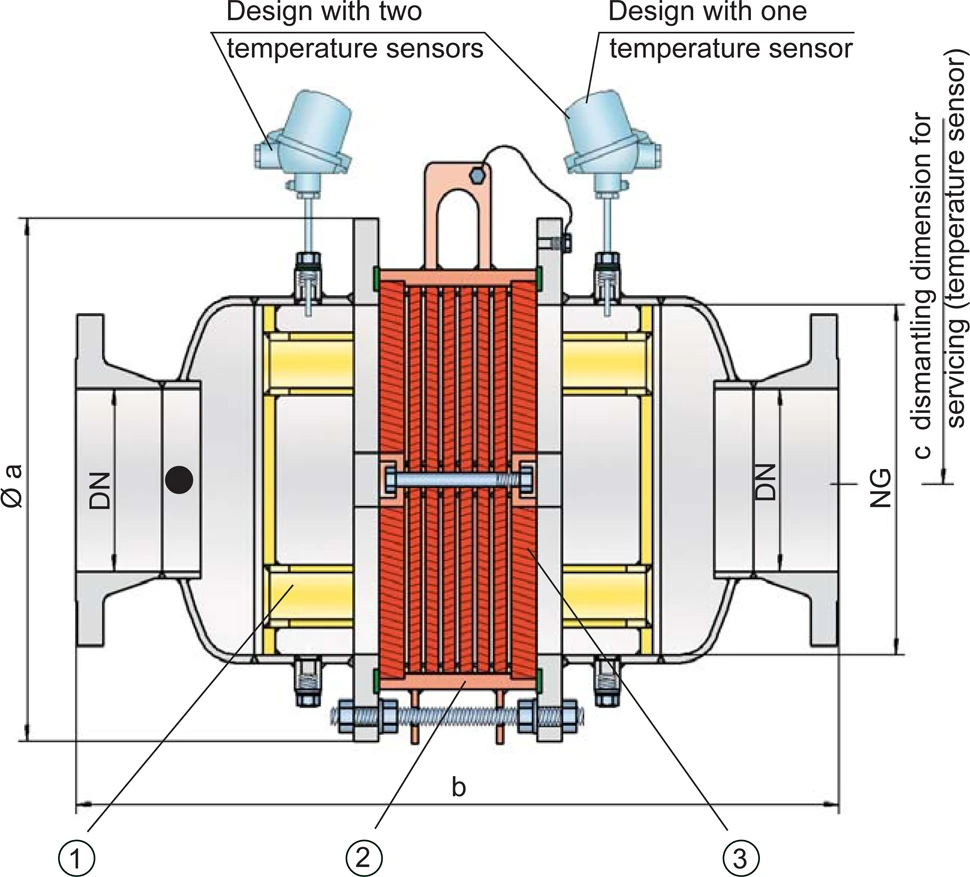
Dimensions
To select nominal width/ nominal size Nominal size The nominal size is an alphanumeric designation of size for components in a piping system, used for reference purposes, comprising the letters DN followed by a dimensionless integer that is indirectly related to the physical size of the bore or outside diameter of the connections, expessed in millimeters. (NG/DN) - combination, please use the flow capacity charts on the following pages. Additional nominal width/nominal size (NG/DN) - combinations for improved flow capacity upon request.
| NG | 150 / 6" | 150 / 6" | 200 / 8" | 300 / 12" | 400 / 16" | 500 / 20" | 600 / 24 | 700 / 28" | 800 / 32" | 1000 / 40" | 1200 / 48" |
| DN | ≤ 50 / 2" | 65, 80 / 2 ½“, 3 | ≤ 100 / 4" | ≤ 150 / 6" | ≤ 200 / 8" | ≤ 250 / 10" | ≤ 300 / 12" | ≤ 350 / 14" | ≤ 400 / 16" | ≤ 500 / 20" | ≤ 600 / 24" |
| a | 285 / 11.22 | 285 / 11.22 | 340 / 13.39 | 460 / 18.11 | 580 / 22.83 | 715 / 28.15 | 840 / 33.07 | 1025 / 40.35 | 1025 / 40.35 | 1255 / 49.41 | 1485 / 58.46 |
| b | 650 / 25.59 | 650 / 25.59 | 700 / 27.56 | 800 / 31.50 | 900 / 35.43 | 1100 / 43.31 | 1250 / 49.21 | 1500 / 59.06 | 1500 / 59.06 | 1700 / 66.93 | 2000 / 78.74 |
| c | 300 / 11.81 | 300 / 11.81 | 330 / 12.99 | 380 / 14.96 | 490 / 19.29 | 540 / 21.26 | 590 / 23.23 | 690 / 27.17 | 690 / 27.17 | 790 / 31.10 | 880 / 34.65 |
Dimensions in mm / inches
Selection of explosion group
| MESG | Expl. Gr. (IEC / CEN) | Gas Group (NEC) |
| > 0,90 mm | IIA | D |
| ≥ 0,65 mm | IIB3 | C |
Special approvals upon request
Selection of max. operating pressure
| Expl. Gr. | DN | 50 / 2" | 80 / 3" | 100 / 4" | 150 / 6" | 200 / 8" | 250 / 10" | 300 / 12" | 350 / 14" | 400 / 16" | 500 / 20" | 600 / 24" |
| NG | 150 / 6'' | 150 / 6'' | 200 / 8'' | 300 / 12'' | 400 / 16'' | 500 / 20'' | 600 / 24'' | 700 / 28'' | 800 / 32'' | 1000 / 40'' | 1200 / 48'' | |
| IIA (D) | Pmax | 1,2 / 17.4 | 1,2 / 17.4 | 1,2 / 17.4 | 1,2 / 17.4 | 1,2 / 17.4 | 1,2 / 17.4 | 1,2 / 17.4 | 1,2 / 17.4 | 1,2 / 17.4 | 1,2 / 17.4 | 1,2 / 17.4 |
| IIB3 (C) | Pmax | 1,6 / 23.2 | 1,6 / 23.2 | 1,6 / 23.2 | 1,6 / 23.2 | 1,6 / 23.2 | 1,6 / 23.2 | 1,6 / 23.2 | 1,6 / 23.2 | 1,6 / 23.2 | 1,6 / 23.2 | 1,6 / 23.2 |
Pmax = maximum allowable operating pressure in bar / psi absolute, higher operating pressure upon request
Specification of max. operating temperature
| ≤ 60°C / 140°F | Tmaximum allowable operating temperature in °C |
| - | Designation |
higher operating temperatures upon request
Material selection for housing
| Design | A | B |
| Housing | Steel | Stainless Steel |
| Gasket | PTFE | PTFE |
| Flame arrester unit Flame arrester unit Flame arrester casing with FLAMEFILTER® set. | A | B |
Special materials upon request
Material combinations of flame arrester unit
| Design | A | B |
| FLAMEFILTER® cage | Steel | Stainless Steel |
| FLAMEFILTER®* | Stainless Steel | Stainless Steel |
| Spacer Spacer The spacer is a component that is generally used in a PROTEGO® flame arrester as a spacer within the FLAMEFILTER® se | Stainless Steel | Stainless Steel |
*the FLAMEFILTER® are also available in the materials Tantalum, Inconel, Copper, etc. when the listed housing and cage materials are used.
Special materials upon request
Flange connection type
| EN 1092-1; Form B1 |
| ASME B16.5 CL 150 R.F. |
other connections upon request
Flow Capacity Chart
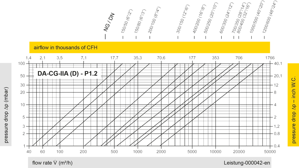
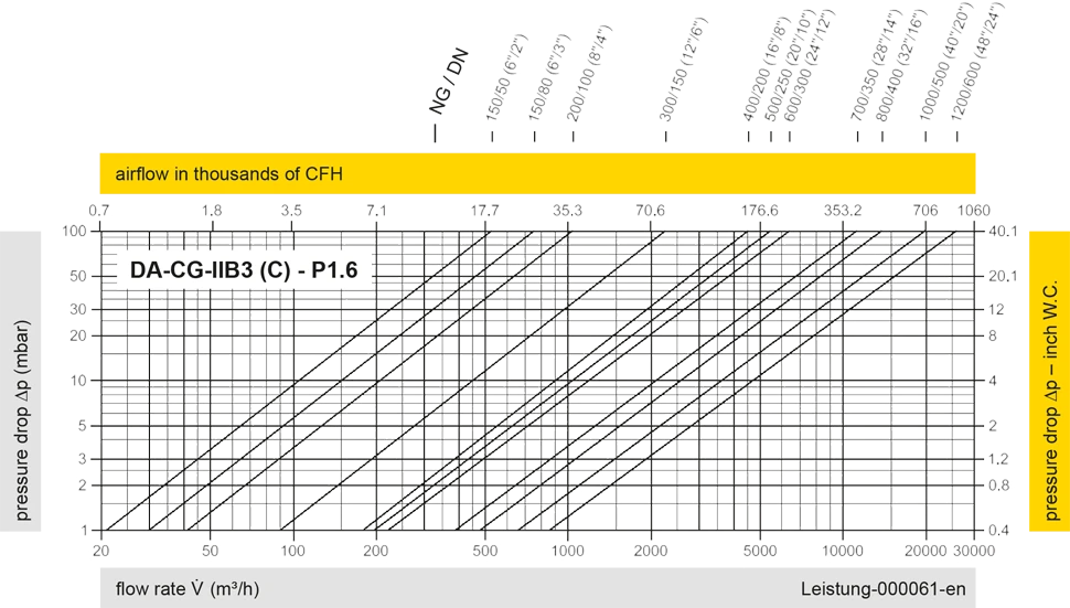
The flow capacity charts have been determined with a calibrated and TÜV certified flow capacity test rig. Volume flow V in (m³/h) and CFH refer to the standard reference conditions of air ISO 6358 (20°C, 1bar). For conversion to other densities and temperatures refer to Sec. 1: “Technical Fundamentals”.


Contact CSR Department
