FA-G-IIA1-P2.2

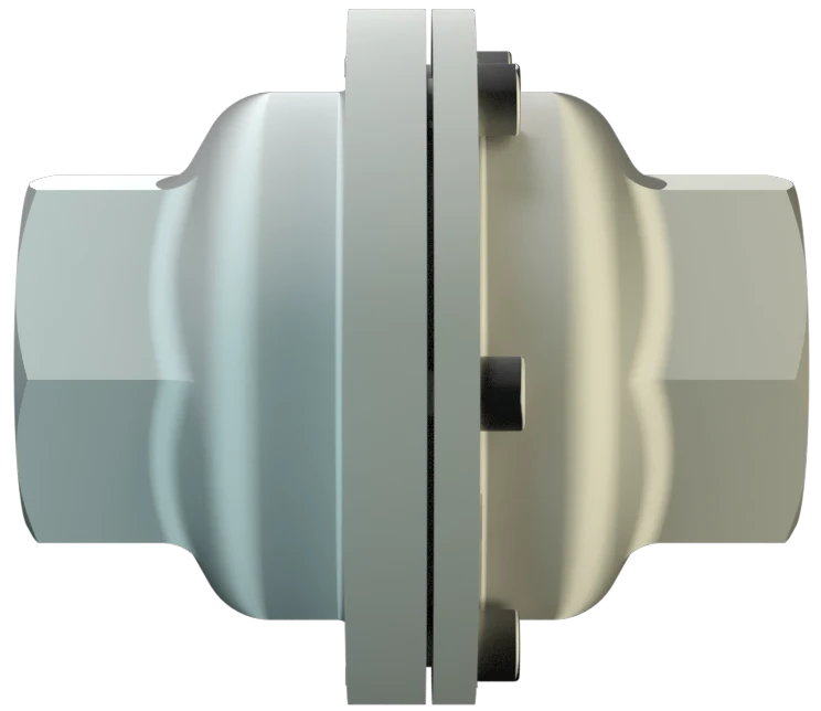
In-Line Deflagration Flame Arrester for biogas, sewage gas and landfi ll gas, concentric design, bidirectional, endurance burning proof (under atmospheric conditions)

Features

Modular Design
Allows Replacement and Cleaning of Single FLAMEFILTER®
Fastest Disassembly and Assembly
of Single FLAMEFILTER®
Pipe Thread Connection
Bi-Directional Flame Transmission
Proof Design
Provides Safety
Protects Against Deflagrations for All Explosion Groups IIA, IIB3 and IIC (NEC Groups D, C and B)
Spare Parts
Cost-Effective Spare Parts
Function and Description

Protection of Fuel Supply Lines

The Pressure/vacuum relief valve Pressure/vacuum relief valve is an umbrella term that includes pressure or vacuum relief valve as well as pressure and vacuum relief valve. PROTEGO® FA-G-IIA1-P2.2 In-Line Deflagration Flame Arrester Deflagration flame arrester Flame arrester designed to prevent the transmission of a deflagration. It can be an end-of-line flame arrester or an in-line flame arrester. was specially developed for bio-, sewage- and landfill-gas applications. The compact design of the PROTEGO® FA-G makes it the state of the art technology for installation in pipes with diameters of ½” up to 2”. The devices are installed with minimal distance to the burner to prevent flashback Flashback Phenomenon occurring in a flammable mixture of air and gas when the local velocity of the combustible mixture becomes less than the flame velocity, causing the flame to travel back to the point of mixture. in to the fuel feed lines. When installing the deflagration Deflagration Explosion propagating at subsonic velocity (EN 1127-1:1997). flame arrester Flame arrester Device fitted to the opening of an enclosure, or to the connecting pipe work of a system of enclosures, and whose intended function is to allow flow but prevent the transmission of a flame. , make sure that the distance between potential ignition sources and the location of the installed device Device A device is a pipe component that influences the media flow by opening, closing, or partially shutting off the flow channel or by dividing or mixing the media flow. , does not exceed the L/D ratio (pipe length/pipe diameter), for which the device was approved. As per EN ISO 16852 the L/D ratio is limited to (L/D) max ≤ 50 for Deflagration Flame Arresters of explosion Explosion Abrupt oxidation or decomposition reaction producing an increase in temperature, pressure, or in both simultaneously. group IIA1.

For Explosion Group IIA1 - Methan

The In-Line Deflagration Flame Arresters is symmetrical and offers bidirectional flame transmission protection. The device consists of two housing Housing A housing is a solid shell, which surrounds a content, either protecting the content from external influences, or protecting the environment from the content. parts (1) and two FLAMEFILTER® (2) in the center. The PROTEGO® FA-G-IIA1-P2.2 Flame Arrester protects against deflagrations and endurance burning Endurance burning Stabilized burning for an unlimited time. (under atmospheric condition Atmospheric conditions Atmospheric conditions are pressures from 80 kPa till 110 kPa and temperatures from -20°C up to +60°C. ) and short time burning Short time burning Stabilized burning for a specific time. for 1 min. for the maximum operating conditions of explosion group IIA1 - Methane.

Many Individual Certifications
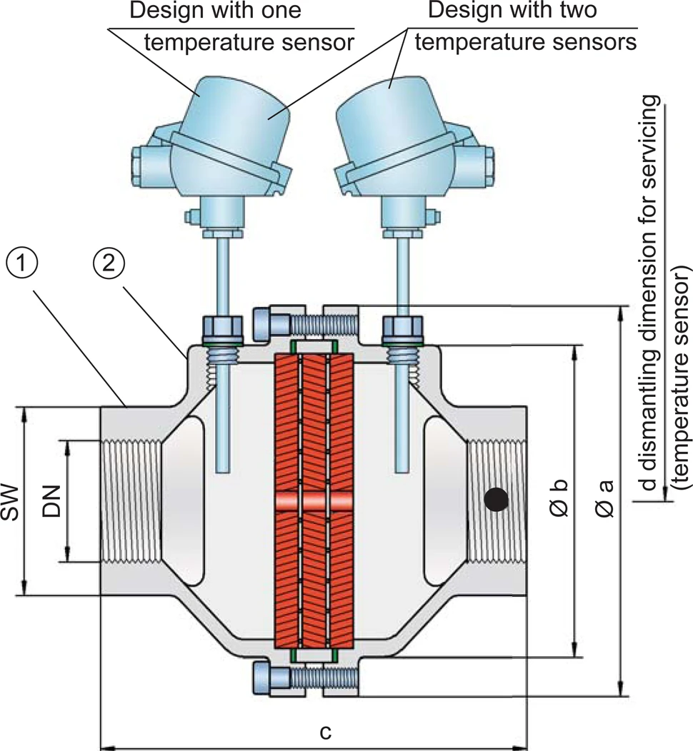
PROTEGO® FA-G devices for substances of explosion groups IIA, IIB3 and IIC (NEC groups D, C, and B) are shown on separate pages. The standard design can be used up to an operating temperature Operating temperature Temperature reached when the equipment is operating under design conditions. of +60°C / 140°F and an absolute operating pressure Operating pressure Operating pressure is the pressure existing at normal operating conditions within the system being protected. up to 2.2 bar / 31.9 psi. EU conformity according to the currently valid ATEX directive. Approvals according to other national/international regulations on request.
Product Data

Dimensions

To select the nominal size Nominal size The nominal size is an alphanumeric designation of size for components in a piping system, used for reference purposes, comprising the letters DN followed by a dimensionless integer that is indirectly related to the physical size of the bore or outside diameter of the connections, expessed in millimeters. (DN), use the flow capacity charts on the following pages

DNG ½G ¾G 1G 1 ¼G 1 ½G 2
a 80/3.15 80/3.15 100/3.94 100/3.94 155/6.10 155/6.10
b 55/2.16 55/2.16 76/2.99 76/2.99 124/4.88 124/4.88
c 100/3.94 100/3.94 110/4.33 110/4.33 170/6.69 170/6.69
d -— 400/15.75 400/15.75
SW 32/1.26 32/1.26 50/1.97 50/1.97 75/2.95 75/2.95

Dimensions in mm / inches, SW= width across flats

Selection of explosion group

MESGExpl. Gr. (IEC / CEN)
≥ 1,14 mmIIA1

Special approvals upon request

Selection of max. operating pressure

Expl. GrDNG ½G ¾G 1G 1 ¼G 1 ½G 2
IIA1 Pmax 2,2/31.9 2,2/31.9 2,2/31.9 2,2/31.9 2,2/31.9 2,2/31.9

Pmax = maximum allowable operating pressure in bar / psi absolute, higher operating pressure upon request

Specification of max. operating temperature

≤ 60°C / 140°FTmaximum allowable operating temperature in °C
-Designation

higher operating temperatures upon request

Material selection

DesignBC
HousingStainless SteelHastelloy
GasketPTFEPTFE
FLAMEFILTER®*Stainless SteelHastelloy

* the FLAMEFILTER® is also available in the materials Tantalum, Inconel, Copper, etc. when the listed housing materials are used.

Special materials upon request

Type of connection

Pipe thread DIN ISO 228-1DIN

other types of thread upon request

Flow Capacity Chart

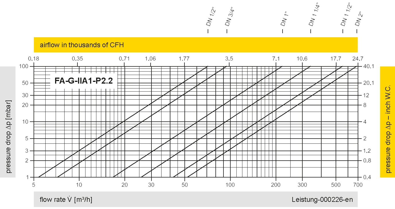
The flow capacity charts have been determined with a calibrated and TÜV certified flow capacity test rig. Volume flow V in (m³/h) and CFH refer to the standard reference conditions of air ISO 6358 (20°C, 1bar). For conversion to other densities and temperatures refer to Sec. 1: “Technical Fundamentals”.

Applications

Processing Facilities

Vapor Combustion Systems

Tank Storage

Alcohol Storage Tanks

Contact CSR Department 

Picture of Auris-Nadine Hillen
Auris-Nadine Hillen

CSR Department

+49 (0)5307 809 108