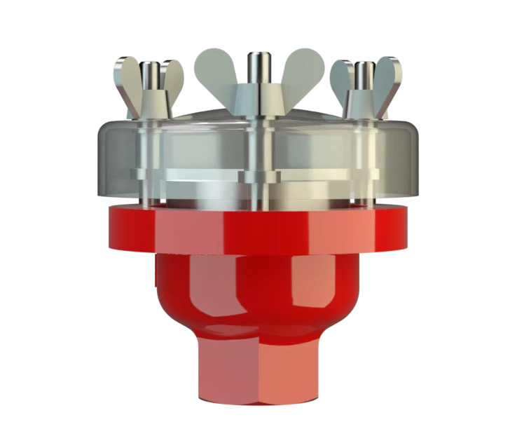
EB-Z
Deflagration Flame Arrester, endurance burning proof, End-of-Line
Features
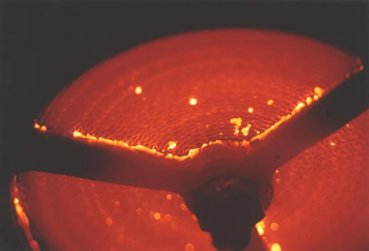
Safety Against Deflagrations and Hydrocarbon Fires
Comprehensive Weather Protection
Modular Design
Easy Maintenance
Low Costs
Spare Parts
Protection Against Atmospheric Deflagration and Endurance Burning
Main Component – PROTEGO® Flame Arrester Unit

Many Individual Certifications
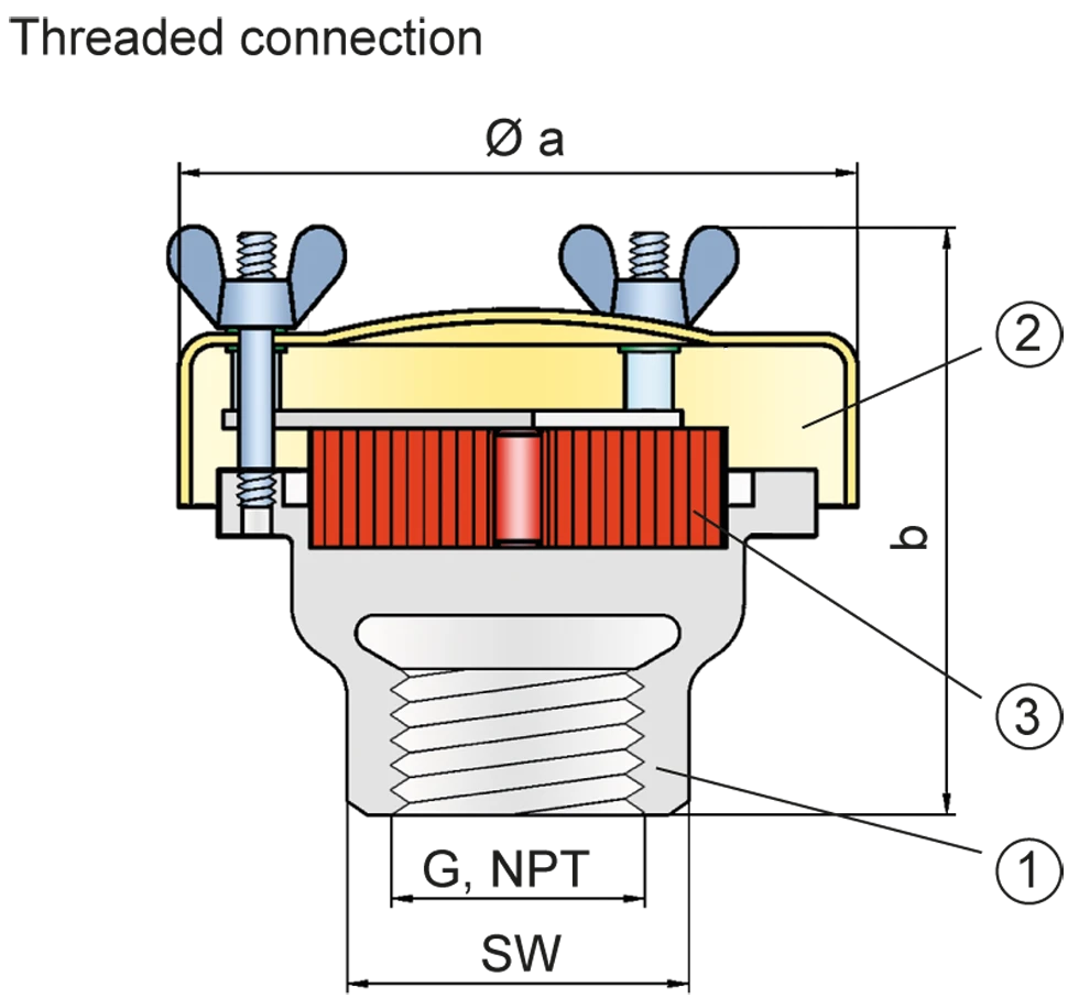
Dimensions
To select the nominal size Diámetro nominal The nominal size is an alphanumeric designation of size for components in a piping system, used for reference purposes, comprising the letters DN followed by a dimensionless integer that is indirectly related to the physical size of the bore or outside diameter of the connections, expessed in millimeters. (DN), please use the flow capacity chart
| DN/ G, NPT | 15 / ½“ | 20 / ¾" | 25 / 1“ | 32 / 1¼“ |
| a | 87 | 87 | 114 | 114 |
| b | 93 | 93 | 98 | 98 |
| b* | 123 | 123 | 123 | 123 |
| SW | 32 | 32 | 50 | 50 |
Dimensions in mm / inches, SW= width across flats
Selection of explosion group
| MESG | Expl. Gr. (IEC / CEN) | Gas Group (NEC) |
| > 0,90 mm | IIA | D |
Special approvals upon request
Material selection
| Design | B |
| Housing | Stainless Steel |
| Weather Hood | Acrylic glass |
| FLAMEFILTER® | Stainless Steel |
Special materials upon reques
Type of connection
| Pipe thread DIN ISO 228-1 |
| EN 1092-1; Form B1 |
| ASME B16.5 CL 150 R.F. |
other types upon request
Flow Capacity Chart
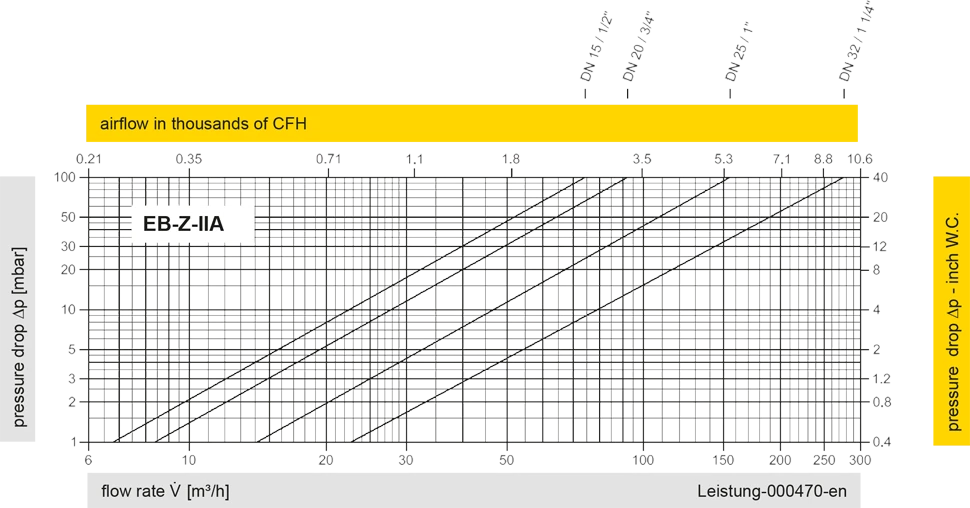
The flow capacity charts have been determined with a calibrated and TÜV certified flow capacity test rig. Volume flow V in (m³/h) and CFH refer to the standard reference conditions of air ISO 6358 (20°C, 1bar). For conversion to other densities and temperatures refer to Sec. 1: “Technical Fundamentals”.


Contact CSR Department
