DR/ES
Detonationsrohrsicherung für stabile Detonationen und Deflagrationen in Eckausführung mit Stoßfang, einseitig wirkend
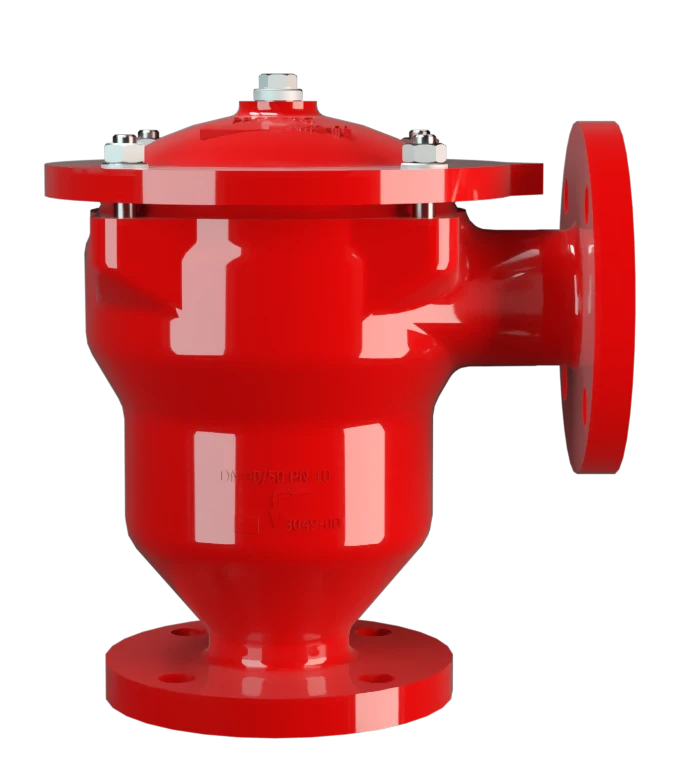
Merkmale
Geringe Anzahl an FLAMMENFILTER® Scheiben
Schnellste Demontage und Montage
Modularer Aufbau
Eckkonstruktion
Erweiterter Anwendungsbereich
Ersatzteile
Niedrige Kosten
Wartungs- und Kostenvorteile

Hauptbestandteil - PROTEGO® Flammensicherung

Viele individuelle Zulassungen
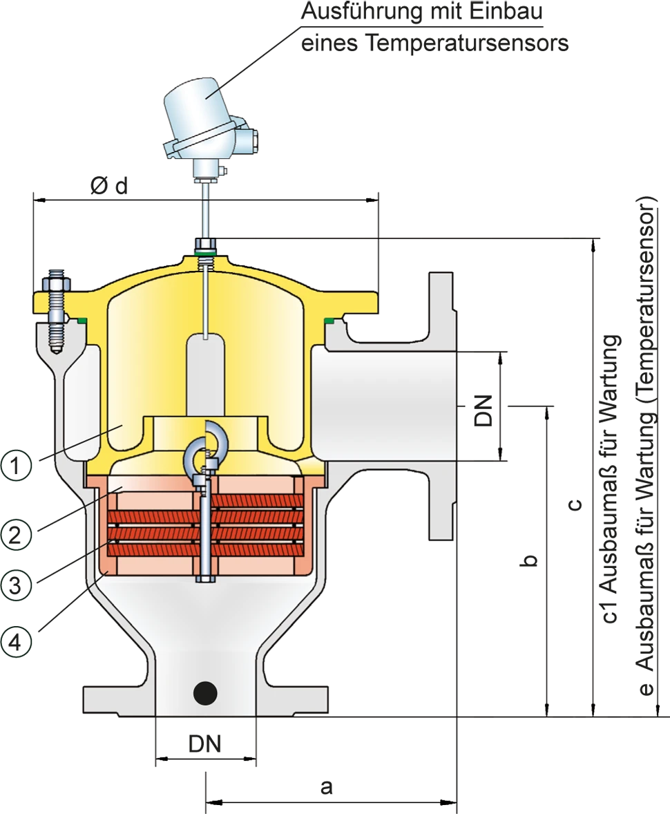
Maßtabelle
Zur Auswahl der Nennweite (DN) benutzen Sie bitte die Volumenstromdiagramme auf den folgenden Seiten
| DN | 25 / 1" | 32 / 1¼" | 40 / 1½" | 50 / 2" | 65 / 2 ½" | 80 / 3" | 100 / 4" | 125 / 5" | 150 / 6" | 200 / 8“ |
| a | 125 | 125 | 153 | 155 | 198 | 200 | 250 | 332 | 335 | 425 |
| b | 140 | 140 | 183 | 185 | 223 | 225 | 290 | 357 | 360 | 505 |
| c | 210 | 210 | 290 | 290 | 365 | 365 | 415 | 535 | 535 | 810 |
| c1 | 285 | 285 | 395 | 395 | 500 | 500 | 595 | 750 | 750 | 1230 |
| d | 150 | 150 | 210 | 210 | 275 | 275 | 325 | 460 | 460 | 620 |
| e | 495 | 495 | 600 | 600 | 705 | 705 | 795 | 950 | 950 | 1435 |
Abmessungen in mm
Auswahl der Explosionsgruppe
| MESG | Expl. Gr. (IEC / CEN) | Gas Group (NEC) |
| > 0,90 mm | IIA | D |
| ≥ 0,65 mm | IIB3 | C |
Sonderabnahmen auf Anfrage
Auswahl des maximalen Betriebsdrucks
| Expl. Gr. | DN | 25 / 1" | 32 / 1¼" | 40 / 1½" | 50 / 2" | 65 / 2½" | 80 / 3" | 100 / 4" | 125 / 5" | 150 / 6" | 200 / 8“ |
| IIA | Pmax | 4,0 | 4,0 | 4,0 | 4,0 | 2,9 | 2,9 | 2,0 | 2,0 | 2,0 | 1,2 |
| IIB3 | Pmax | 3,0 | 3,0 | 2,0 | 2,0 | 2,0 | 2,0 | 1,5 | 1,4 | 1,4 | 1,1 |
Pmax = maximal zulässiger Betriebsdruck in bar absolut, höherer Betriebsdruck auf Anfrage
Angabe der max. Betriebstemperatur
| ≤ 60°C | Tmaximal zulässige Betriebstemperatur in C° |
| - | Kennzeichnung |
höhere Betriebstemperaturen auf Anfrage
Materialauswahl für Gehäuse
| Ausführung | B | C | D |
| Gehäuse | Stahl | Edelstahl | Hastelloy |
| Heizmantel (DR / ES-H-(T)-...) | Stahl | Edelstahl | Edelstahl |
| Deckel mit Stoßfang | Stahl | Edelstahl | Hastelloy |
| O-Ring | FPM* | PTFE | PTFE |
| Flammensicherung | A | C, D | E |
* für Geräte bei Einsatz mit erhöhten Temperaturen ab 150°C (T150) Dichtungen aus PTFE. Das Gehäuse und der Deckel mit Stoßfang können auch in Werkstoff Stahl mit ECTFE-Beschichtung geliefert werden.
Sonderwerkstoffe auf Anfrage
Materialkombinationen der Flammensicherung
| Ausführung | A | C | D | E |
| FLAMMENFILTER® Käfig | Stahl | Edelstahl | Edelstahl | Hastelloy |
| FLAMMENFILTER®* | Edelstahl | Edelstahl | Hastelloy | Hastelloy |
| Zwischenlagen | Edelstahl | Edelstahl | Hastelloy | Hastelloy |
* die FLAMMENFILTER® sind auch in den Werkstoffen Tantal, Inconel, Kupfer usw. bei Verwendung der aufgeführten Gehäuse- bzw. Käfigwerkstoffe lieferbar.
Sonderwerkstoffe auf Anfrage
Flanschanschlussart
| EN 1092-1; Form B1 |
| ASME B16.5 CL 150 R.F. |
andere Anschlüsse auf Anfrage
Volumenstromdiagramm
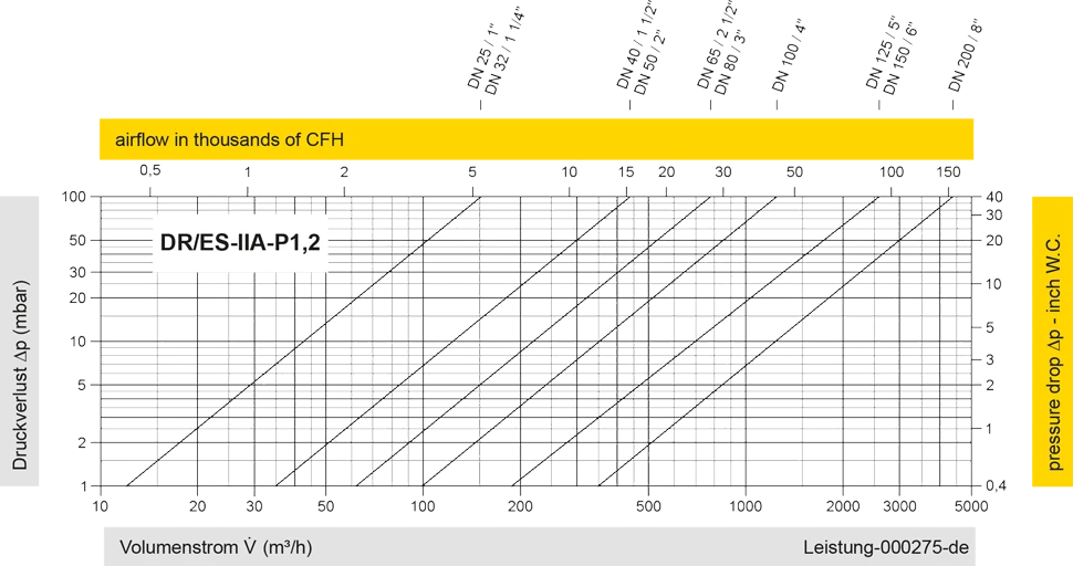
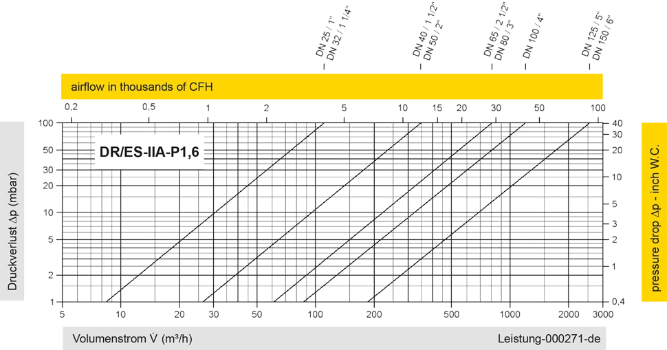
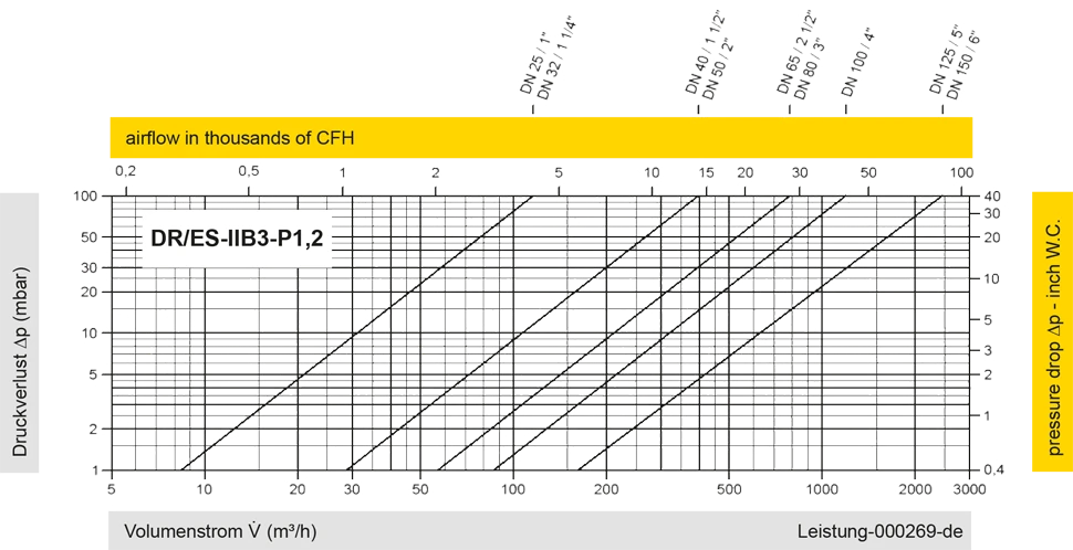
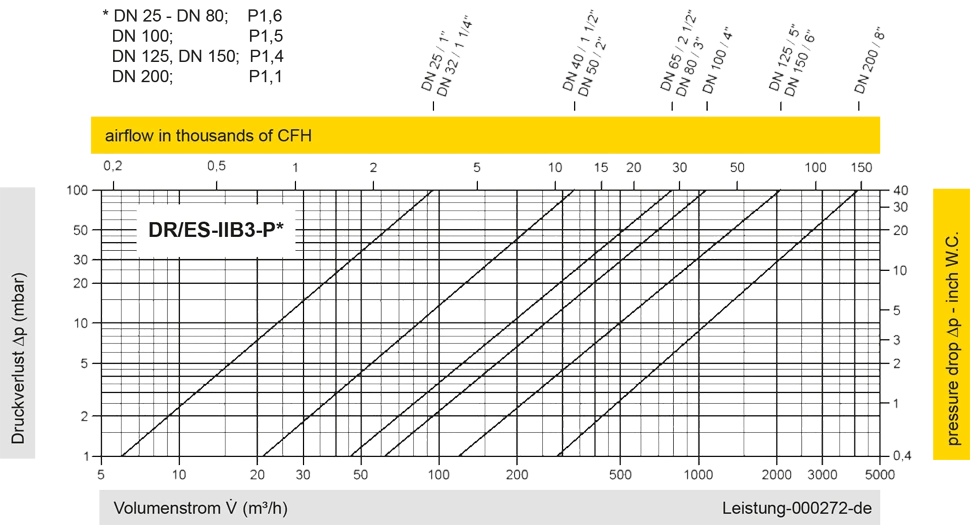
Diese Volumenstromdiagramme sind mit einer kalibrierten und TÜV-zertifizierten Strömungsmessanlage ermittelt worden. Der Volumenstrom V in m³/h bezieht sich auf den technischen Normzustand von Luft nach ISO 6358 (20°C, 1bar). Umrechnung auf andere Dichte und Temperatur siehe Kap. 1: Technische Grundlagen.
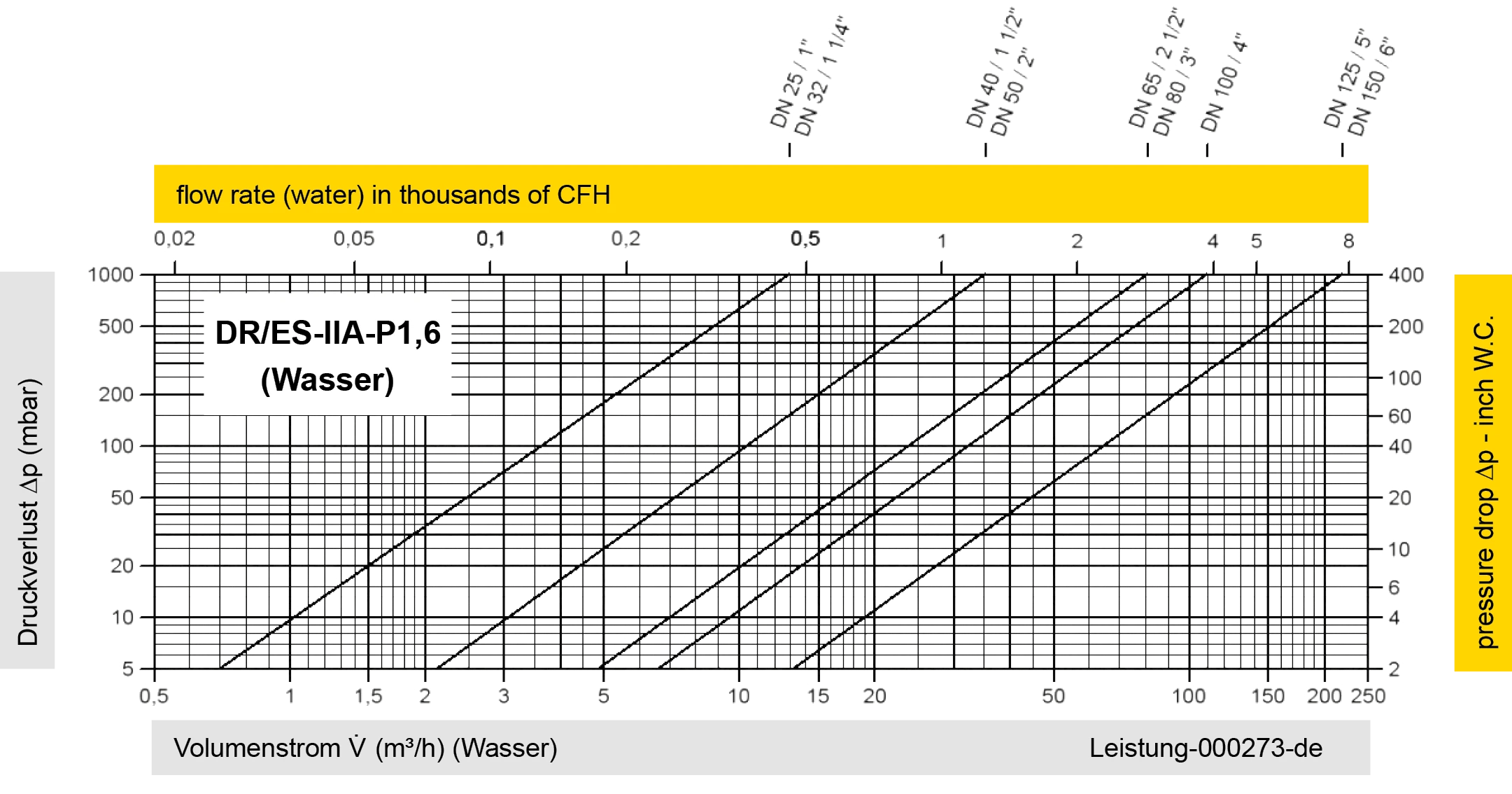
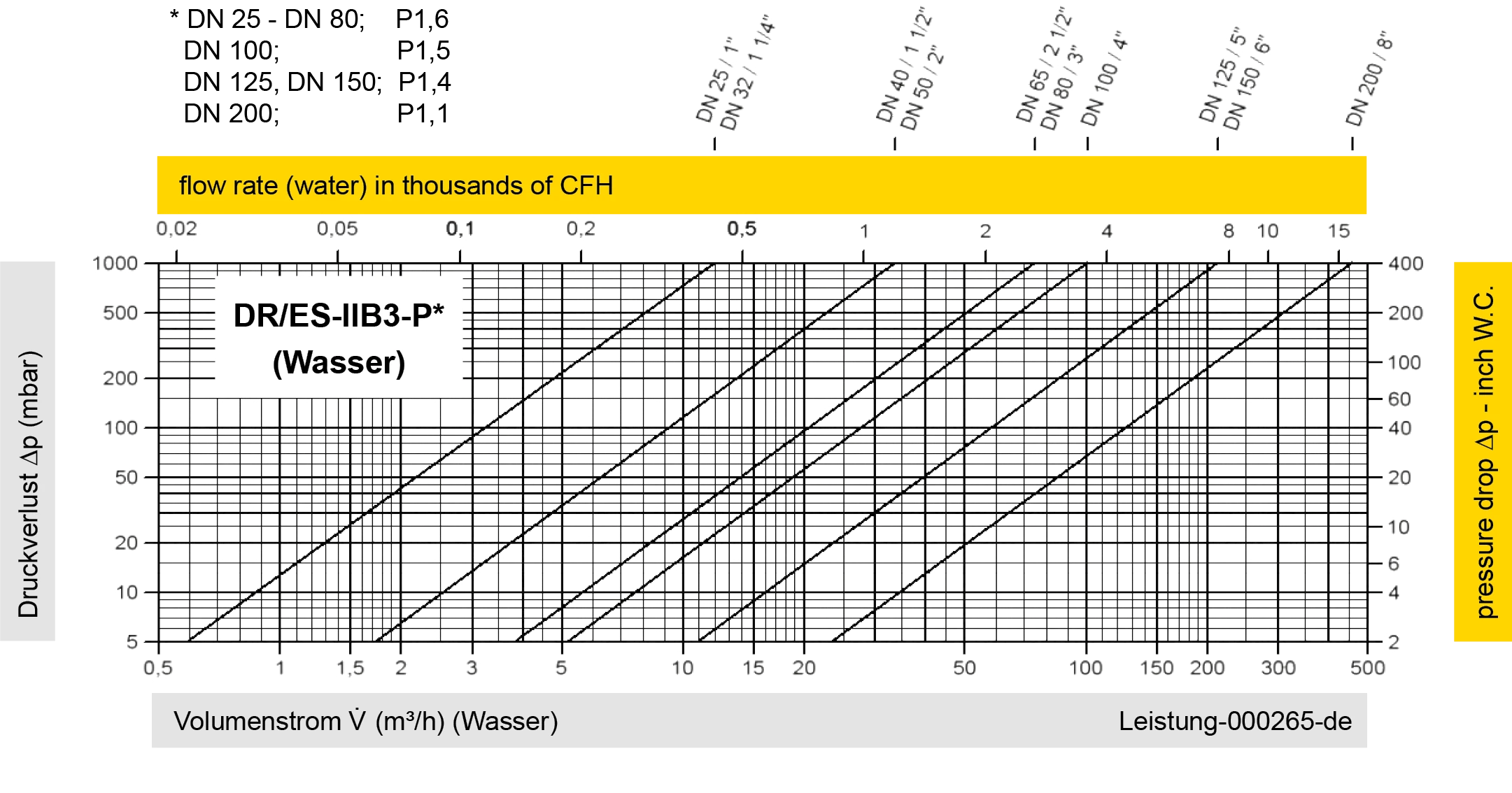
Der Volumenstrom V in m³/h ist mit Wasser ermittelt worden gemäß DIN EN 60534 bei der Temperatur Tn = 20°C und einem Druck pn = 1,013 bar, kinematische Viskosität v = 10-6 m²/s.


Wenn Sie Fragen, Feedback oder weitere Anregungen haben, steht Ihnen unser Expertenteam steht Ihnen gerne zur Verfügung.
