DA-SB
Detonationsrohrsicherung für stabile Detonationen und Deflagrationen in Durchgangsausführung mit Stoßrohr, beidseitig wirkend
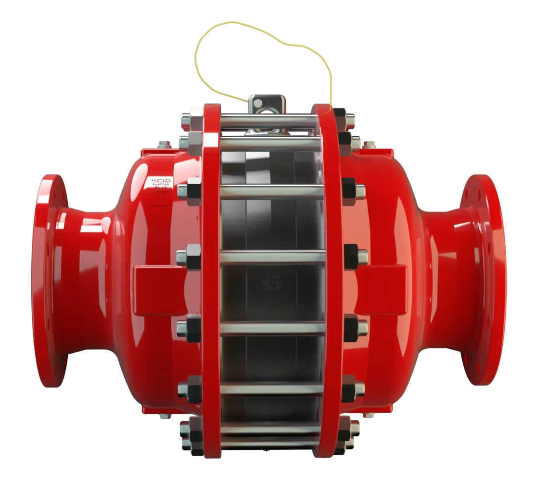
Merkmale
Einsatz von patentierten Stoßrohes (SWGTE)
Optimierte Leistung
Erweiterter Anwendungsbereich
Ersatzteile
Niedrige Kosten
Wartungsfreundliche PROTEGO® Flammensicherungen
Temperatursenoren möglich
Doppelseitige Wirkungsweise
Unterschiedliche Baureihen
Minimale Druckverluste bei maximaler Sicherheit

Hauptbestandteil - PROTEGO® Flammensicherung

Für alle Explosionsgruppen
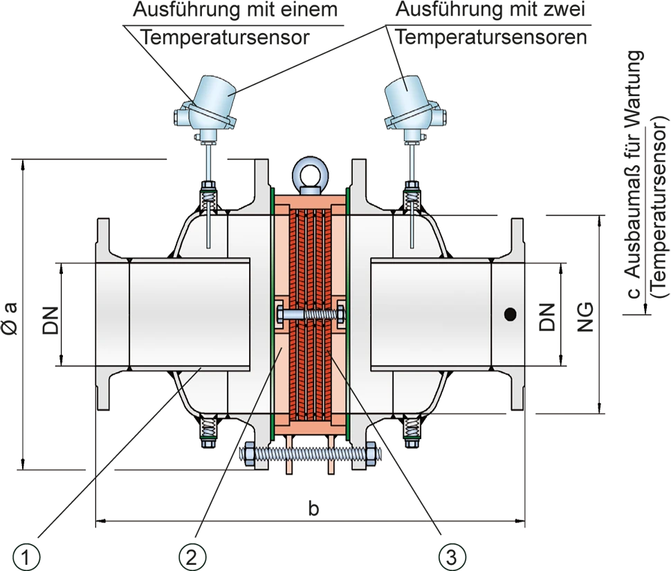
Maßtabelle
Zur Auswahl der Nenngrößen/Nennweiten (NG/DN) - Kombination benutzen Sie bitte die Volumenstromdiagramme auf den folgenden Seiten
weitere Nenngrößen/Nennweiten (NG/DN) - Kombinationen mit verbesserter Strömungsleistung auf Anfrage
| Standard | |||||||||||||
| NG | 150 / 6“ | 150 / 6“ | 200 / 8“ | 300 / 12“ | 400 / 16“ | 500 / 20“ | 600 / 24“ | 700 / 28“ | 800 / 32“ | 1000 / 40“ | 1200 / 48“ | 1600 / 64" | |
| DN | ≤50 / 2" | 65, 80 / 2½", 3" | ≤100 / 4" | ≤150 / 6" | ≤200 / 8" | ≤250 / 10" | ≤300 / 12" | ≤350 / 14" | ≤400 / 16" | ≤500 / 20" | ≤600 / 24" | ≤800 / 32" | |
| a | 285 | 285 | 340 | 445 | 565 | 670 | 780 | 895 | 1015 | 1230 | 1455 | 1915 | |
| b | IIA-P1,1 | 388 | 388 | 476 | 626 | 700 | 800* | 1000* | 1200 | 1400 | 1600 | 1800 | 2200** |
| IIA-P1,4-X3 | 400 | 400 | 488 | 626 | 700 | 800 | 1000 | 1200 | 1400 | ||||
| IIB3-P1,1 | 400 | 412 | 500 | 650 | 724 | 824 | 1000 | 1200 | 1400 | 1600 | 1800 | ||
| IIB3-P1,4-X3 | 412 | 412 | 512 | 650 | 724 | 824 | 1000 | 1200 | 1400 | ||||
| IIC-P1,1 | 400 | 400 | 500 | 638 | 700 | 788 | 1000*** | 1200*** | 1400*** | ||||
| c | 500 | 500 | 520 | 570 | 620 | 670 | 720 | 770 | 820 | 950 | 1050 | 1250 |
Abmessungen in mm
Sondergrößen bis NG 2000/80“, DN 1000/40“ lieferbar
* Maß b für ...-P1,4
** Maß b für ...-P1,2
*** EN 12874
Auswahl der Explosionsgruppe
| MESG | Expl. Gr. (IEC / CEN) | Gas Group (NEC) |
| > 0,90 mm | IIA | D |
| ≥ 0,65 mm | IIB3 | C |
| < 0,50 mm | IIC | B |
Sonderabnahmen auf Anfrage
Auswahl des maximalen Betriebsdrucks
| Expl. Gr. | DN | 50 / 2" | 80 / 3" | 100 / 4" | 150 / 6" | 200 / 8" | 250 / 10" | 300 / 12 " | 350 / 14" | 400 / 16" | 500 / 20'' | 600 / 24" | 800 / 32" |
| NG | 150 / 6'' | 150 / 6'' | 200 / 8'' | 300 / 12'' | 400 / 16'' | 500 / 20'' | 600 / 24'' | 700 / 28'' | 800 / 32'' | 1000 / 40'' | 1200 / 48'' | 1600 / 64'' | |
| IIA | Pmax | 2,1 | 2,1 | 2,1 | 2,1 | 2,1 | 2,1 | 1,4 | 1,4 | 1,4 | 1,1 | 1,1 | 1,2 |
| IIB3 | Pmax | 1,4 | 1,4 | 1,4 | 1,8 | 1,8 | 1,8 | 1,8 | 1,4 | 1,4 | 1,1 | 1,1 | - |
| IIC | Pmax | 2,2 | 2,2 | 1,1 | 1,1 | 1,1 | 1,1 | 1,1* | 1,1* | 1,1* | - | - | - |
Pmax = maximal zulässiger Betriebsdruck in bar absolut, höherer Betriebsdruck auf Anfrage
Zwischengrößen bis Pmax auf Anfrage
* Leistungskurven auf Anfrage
Angabe der max. Betriebstemperatur
| ≤ 60°C | ≤ 200°C | Tmaximal zulässige Betriebstemperatur in C° |
| - | X3 | Kennzeichnung |
höhere Betriebstemperaturen auf Anfrage
Materialauswahl für Gehäuse
| Ausführung | A | B | C |
| Gehäuse | Stahl | Edelstahl | Hastelloy |
| Heizmantel (DA-SB (T)-H-...) | Stahl | Edelstahl | Edelstahl |
| Dichtung | PTFE | PTFE | PTFE |
| Flammensicherung | A, B | B, C, D | D |
Das Gehäuse kann auch in Werkstoff Stahl mit ECTFE- Beschichtung geliefert werden.
Sonderwerkstoffe auf Anfrage
Materialkombinationen der Flammensicherung
| Ausführung | A | B | C | D |
| FLAMMENFILTER® Käfig | Stahl | Edelstahl | Edelstahl | Hastelloy |
| FLAMMENFILTER®* | Edelstahl | Edelstahl | Hastelloy | Hastelloy |
| Zwischenlagen | Edelstahl | Edelstahl | Hastelloy | Hastelloy |
* die FLAMMENFILTER® sind auch in den Werkstoffen Tantal, Inconel, Kupfer usw. bei Verwendung der aufgeführten Gehäuse- bzw. Käfigwerkstoffe lieferbar.
Sonderwerkstoffe auf Anfrage
Flanschanschlussart
| EN 1092-1; Form B1 |
| ASME B16.5 CL 150 R.F. |
andere Anschlüsse auf Anfrage
Volumenstromdiagramm
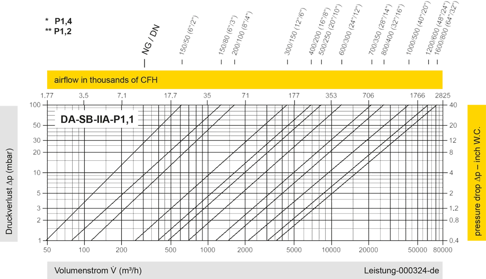
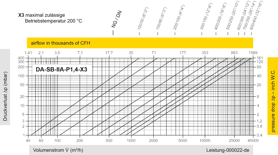
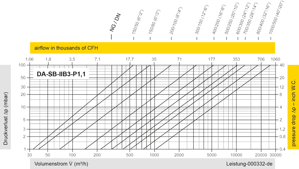
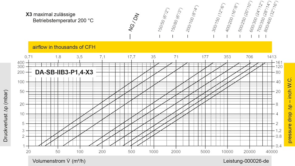
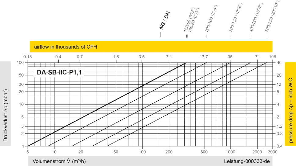
Diese Volumenstromdiagramme sind mit einer kalibrierten und TÜV-zertifizierten Strömungsmessanlage ermittelt worden. Der Volumenstrom V in m³/h bezieht sich auf den technischen Normzustand von Luft nach ISO 6358 (20°C, 1bar). Umrechnung auf andere Dichte und Temperatur siehe Kap. 1: Technische Grundlagen.


Wenn Sie Fragen, Feedback oder weitere Anregungen haben, steht Ihnen unser Expertenteam steht Ihnen gerne zur Verfügung.
