VN-A-PCPF
Pressure/Vacuum Relief Valve, Pilot-operated diaphragm valve
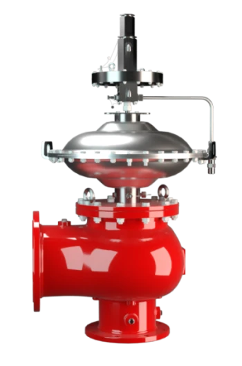
Features
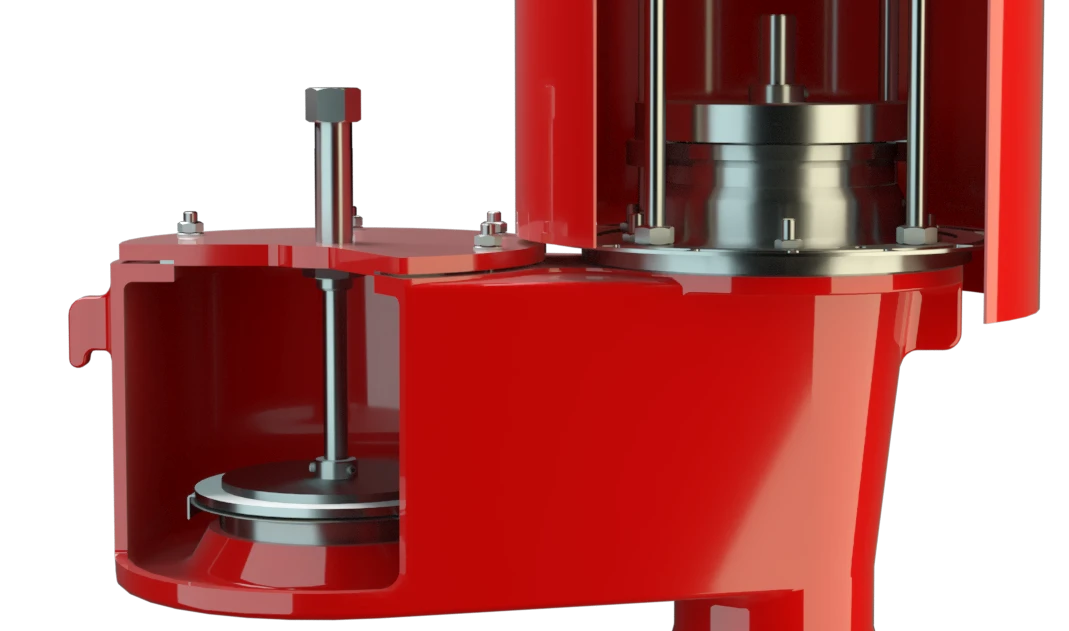
Pilot Operated
Low Emissions
10% Technology
Extreme Tightness
Optimal Pressure Maintenance
High Durability
Flow Capacity
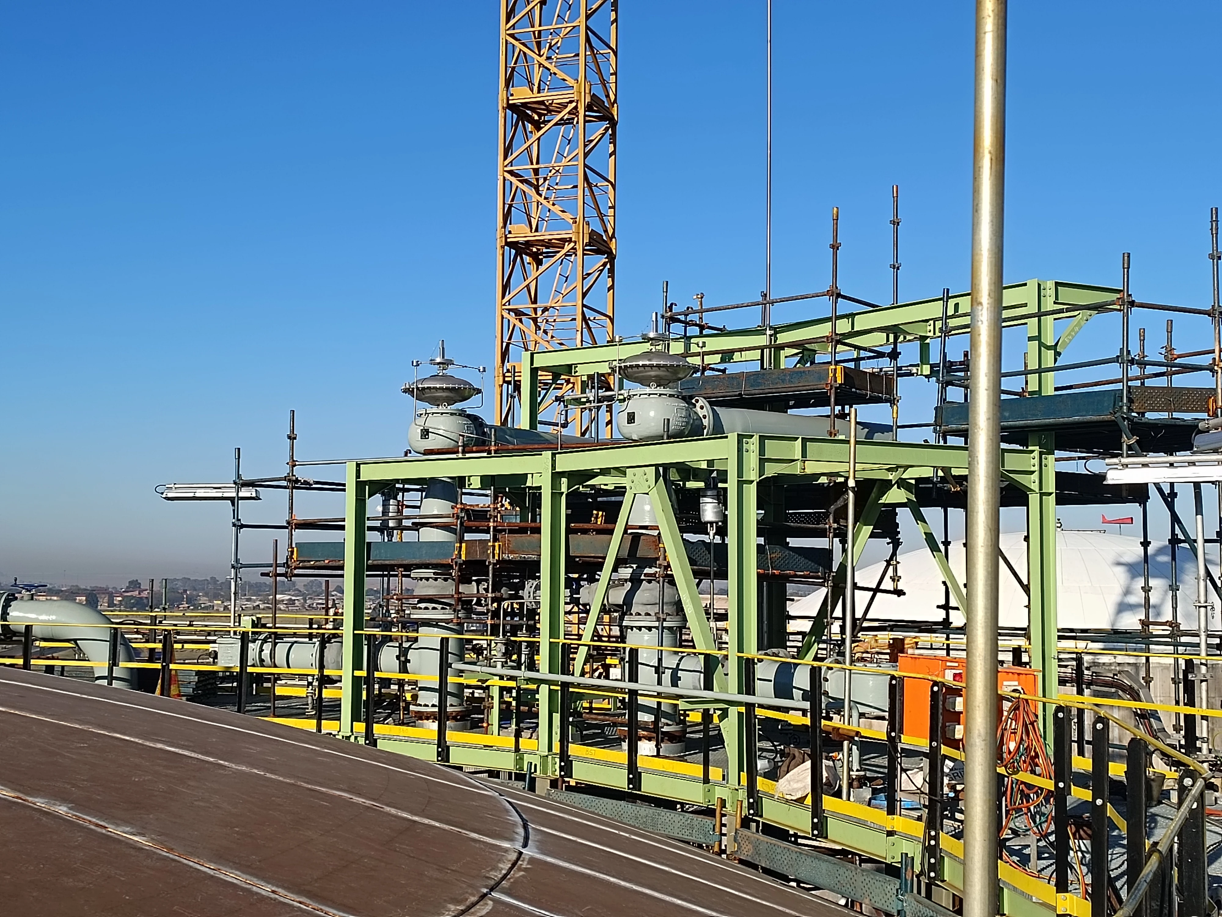
Used in Explosion Hazardous Areas
Field Test Kit
Combined Pressure and Vacuum Relief Valve
Tank Pressure Controls the Pilot Valve
Extreme Thightness
Advanced Manufacturing Technology
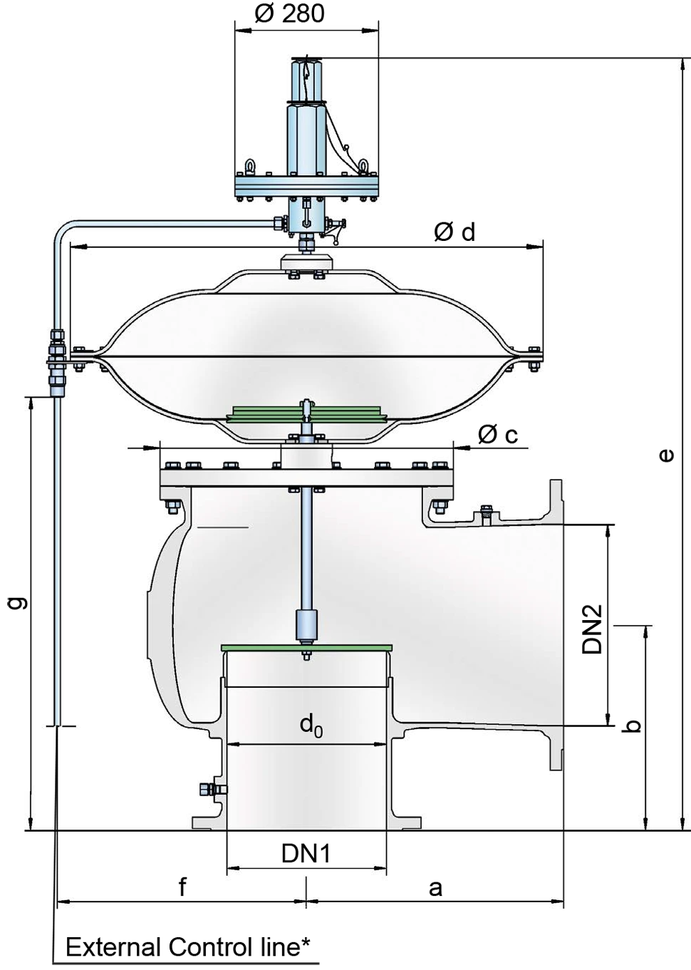
Tabela de dimensões
To select the nominal size Diámetro nominal The nominal size is an alphanumeric designation of size for components in a piping system, used for reference purposes, comprising the letters DN followed by a dimensionless integer that is indirectly related to the physical size of the bore or outside diameter of the connections, expessed in millimeters. (DN), use the flow capacity charts on the folloeing pages
| DN1 | DN2 | a | b | c | d | e | f | g |
| 50 / 2" | 50 / 2" | 175 / 6.89 | 175 / 6.89 | 170 / 6.69 | 360 / 14.17 | 916 / 36.06 | 205 / 8.07 | 343 / 13.53 |
| 50 / 2" | 80 / 3" | 175 / 6.89 | 175 / 6.89 | 170 / 6.69 | 360 / 14.17 | 931 / 36.65 | 205 / 8.07 | 358 / 14.09 |
| 80 / 3" | 80 / 3" | 200 / 7.87 | 200 / 7.87 | 205 / 8.07 | 360 / 14.17 | 957 / 37.68 | 205 / 8.07 | 383 / 15.08 |
| 80 / 3" | 100 / 4" | 200 / 7.87 | 200 / 7.87 | 205 / 8.07 | 360 / 14.17 | 967 / 38.07 | 205 / 8.07 | 393 / 15.47 |
| 100 / 4" | 100 / 4" | 225 / 8.86 | 225 / 8.86 | 250 / 9.84 | 360 / 14.17 | 991 / 39.02 | 205 / 8.07 | 418 / 16.46 |
| 100 / 4" | 150 / 6" | 225 / 8.86 | 225 / 8.86 | 250 / 9.84 | 360 / 14.17 | 1001 / 39.41 | 205 / 8.07 | 428 / 16.85 |
| 150 / 6" | 150 / 6" | 300 / 11.81 | 250 / 9.84 | 335 / 13.19 | 500 / 19.69 | 1104 / 43.46 | 275 / 10.83 | 503 / 19.80 |
| 150 / 6" | 200 / 8" | 300 / 11.81 | 250 / 9.84 | 335 / 13.19 | 500 / 19.69 | 1124 / 44.25 | 275 / 10.83 | 523 / 20.59 |
| 200 / 8" | 200 / 8" | 375 / 14.77 | 300 / 11.81 | 410 / 16.14 | 630 / 24.80 | 1237 / 48.70 | 340 / 13.39 | 610 / 24.02 |
| 200 / 8" | 250 / 10" | 375 / 14.77 | 300 / 11.81 | 410 / 16.14 | 630 / 24.80 | 1267 / 49.88 | 340 / 13.39 | 640 / 25.20 |
| 250 / 10" | 250 / 10" | 425 / 16.73 | 350 / 13.78 | 500 / 19.69 | 790 / 31.10 | 1357 / 53.43 | 420 / 16.54 | 710 / 27.96 |
| 250 / 10" | 300 / 12" | 425 / 16.73 | 350 / 13.78 | 500 / 19.69 | 790 / 31.10 | 1377 / 54.41 | 420 / 16.54 | 730 / 28.74 |
| 300 / 12" | 300 / 12" | 500 / 19.69 | 400 / 15.75 | 570 / 22.44 | 920 / 36.22 | 1468 / 57.80 | 485 / 19.09 | 803 / 31.61 |
| 300 / 12" | 350 / 14" | 500 / 19.69 | 400 / 15.75 | 570 / 22.44 | 920 / 36.22 | 1488 / 58.59 | 485 / 19.09 | 823 / 32.40 |
| 300 / 12" | 400 / 16" | 500 / 19.69 | 400 / 15.75 | 570 / 22.44 | 920 / 36.22 | 1508 / 59.37 | 485 / 19.09 | 843 / 33.19 |
Dimensões em mm
Seleção do material do corpo
| Design | A | B | C |
| Housing | Aluminium | Stainless Steel | LTCS* (Low Temperature Carbon Steel) |
| Valve seat | Stainless Steel | Stainless Steel | Stainless Steel |
| Sealing - housing Carcasa A housing is a solid shell, which surrounds a content, either protecting the content from external influences, or protecting the environment from the content. | PTFE | PTFE | PTFE |
| Sealing – valve disc | metal - to - metal | metal - to - metal | metal - to - metal |
| Housing diaphragm | Stainless Steel | Stainless Steel | Stainless Steel |
| Pilot lines | Stainless Steel | Stainless Steel | Stainless Steel |
| Pilot housing | Aluminium | Aluminium/ Stainless Steel | Aluminium/ Stainless Steel |
| Pilot diaphragm | FEP | FEP | FEP |
* Special materials upon request
Tipo de conexão flangeada
| EN 1092-1; Form B1 |
| ASME B16.5 CL 150 R.F. |
Other types upon request
Coefficient of Discharge
| DN1 | 50 / 2" | 50 / 2" | 80 / 3" | 80 / 3" | 100 / 4" | 100 / 4" | 150 / 6" | 150 / 6" | 200 / 8" | 200 / 8" | 250 / 10" | 250 / 10" | 300 / 12" | 300 / 12" | 300 / 12" |
| DN2 | 50 / 2" | 80 / 3" | 80 / 3" | 100 / 4" | 100 / 4" | 150 / 6" | 150 / 6" | 200 / 8" | 200 / 8" | 250 / 10" | 250 / 10" | 300 / 12" | 300 / 12" | 350 / 14" | 400 / 16" |
| d0 | 54 / 2.13 | 54 / 2.13 | 83 / 3.27 | 83 / 3.27 | 108 / 4.25 | 108 / 4.25 | 160 / 6.30 | 160 / 6.30 | 208 / 8.19 | 208 / 8.19 | 262 / 10.31 | 262 / 10.31 | 310 / 12.20 | 310 / 12.20 | 310 / 12.20 |
| K | 0.57 | 0.83 | 0.75 | 0.79 | 0.69 | 0.85 | 0.7 | 0.8 | 0.65 | 0.8 | 0.62 | 0.76 | 0.62 | 0.72 | 0.8 |
DN1 = size inlet
DN2 = size outlet
d0 = orifice diameter(mm / inches)
K = coefficient of discharge
Diagrama de vazão
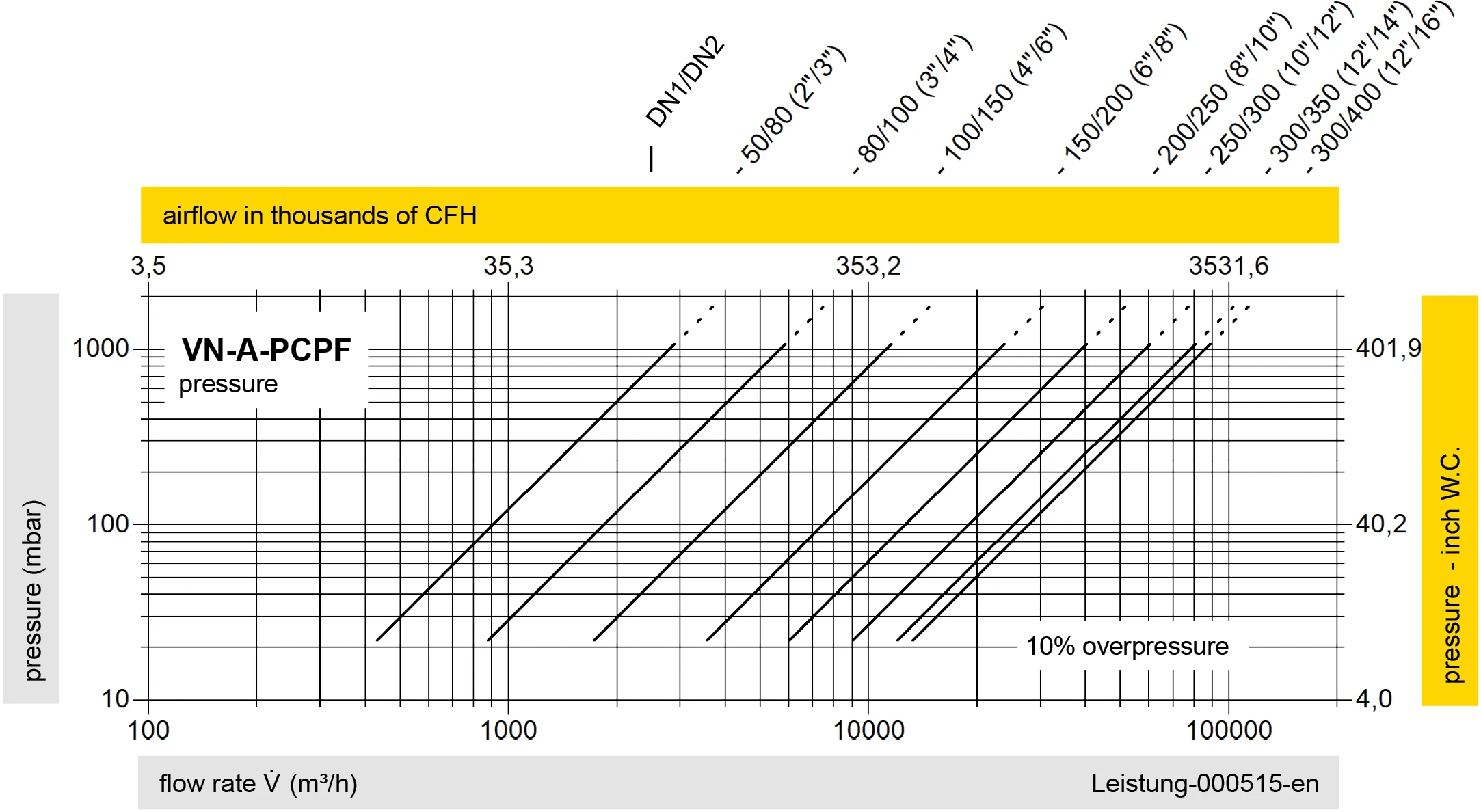

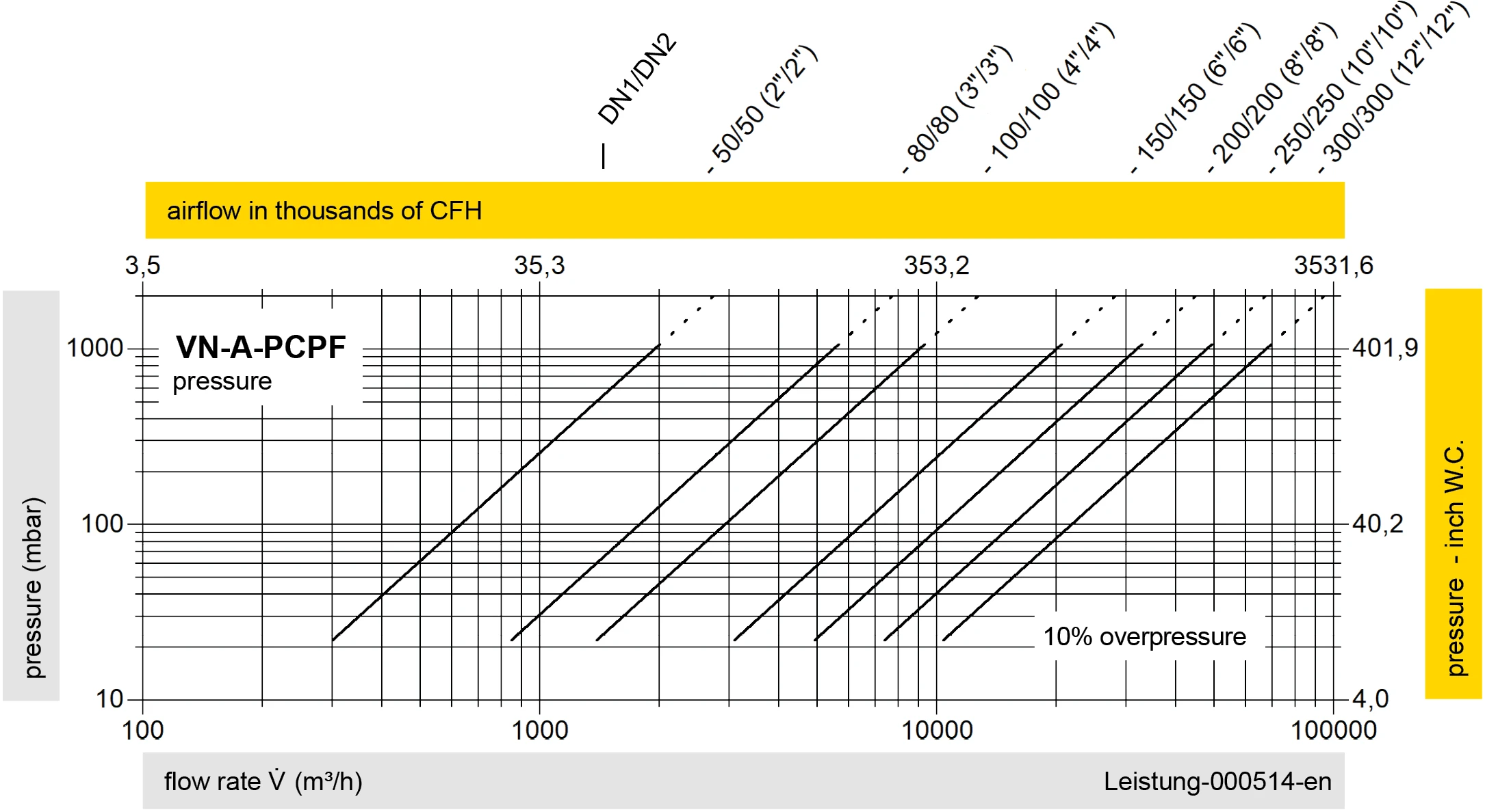
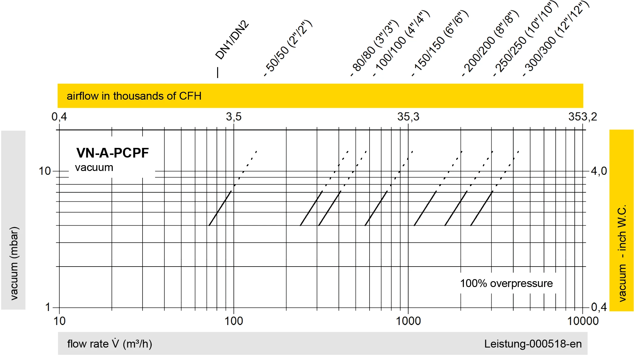
Este diagrama de vazão foi determinado em uma bancada de medição de vazão calibrada e certificada pela TÜV. A vazão V em m³/h se refere ao estado técnico padrão de ar, conforme ISO 6358 (20°C, 1bar). Para conversão em outras densidades e temperaturas, veja o cap. 1: Bases técnicas.
Se você tiver alguma dúvida, comentário ou sugestão, nossa equipe de especialistas terá prazer em ajudá-lo.
