PROTEGO®
Apagallamas a prueba de deflagraciones
Evitar una deflagración en una tubería
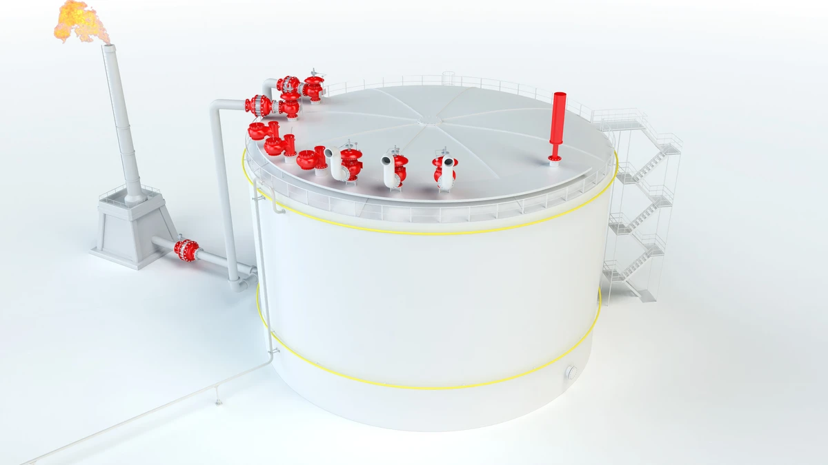
Los Pressure/vacuum relief valve Pressure/vacuum relief valve is an umbrella term that includes pressure or vacuum relief valve as well as pressure and vacuum relief valve. apagallamas a prueba de deflagraciones PROTEGO® se instalan en tuberías y en equipos de proceso y suprimen deflagraciones en sistemas que operan con mezclas explosivas
Están diseñados para instalarse en plantas químicas, petroquímicas, farmacéuticas y otras instalaciones industriales donde no se puede permitir que un frente de llama en una tubería llegue a los equipos ubicados aguas abajo.
Aspectos destacados de los apagallamas PROTEGO® a prueba de Deflagraciones.
Ningún incidente de retroceso
Mayor tiempo de actividad y menores pérdidas
Confianza en el ciclo de vida
El cumplimiento normativo, más sencillo
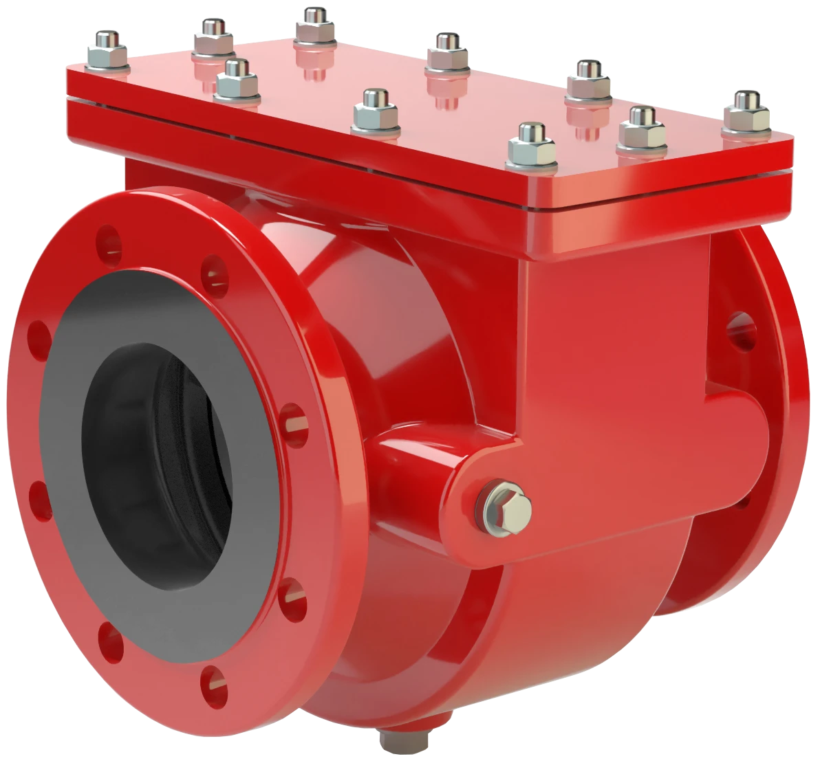
Product Overview
Deflagration vs. Detonation
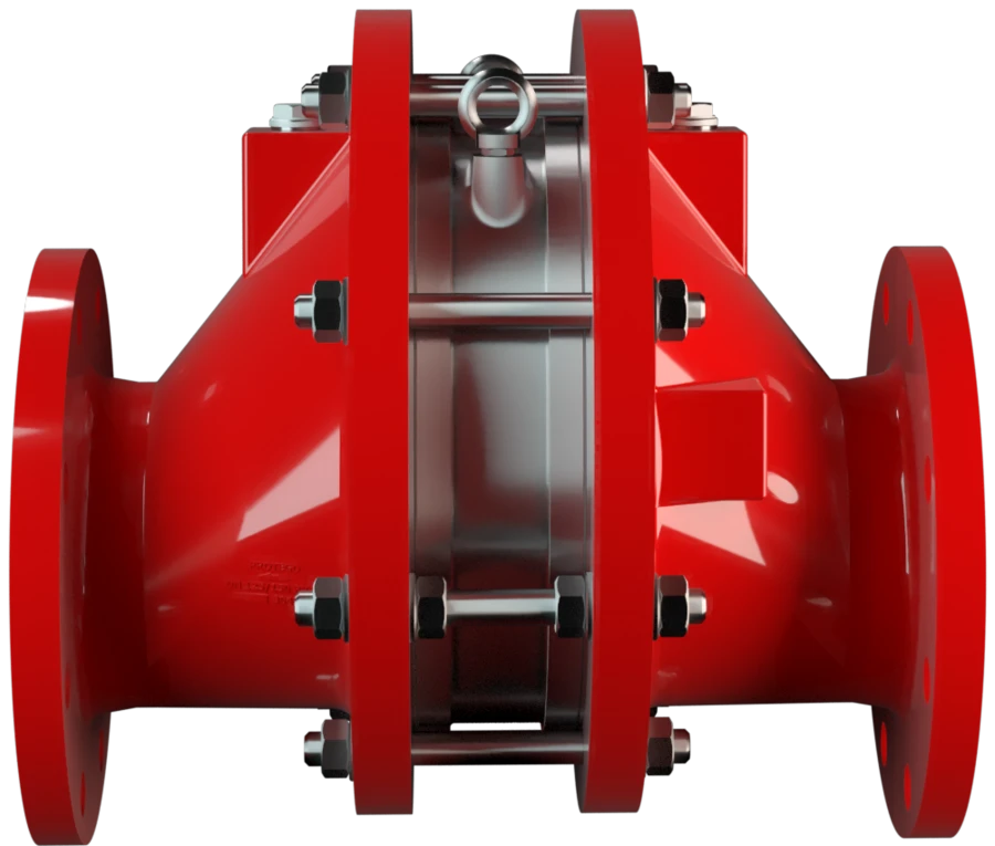
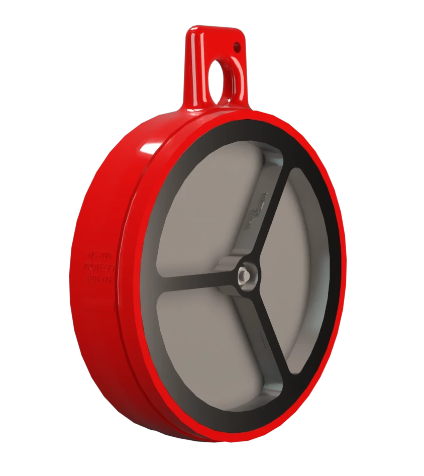
Flame Arrester Unit
Available Options
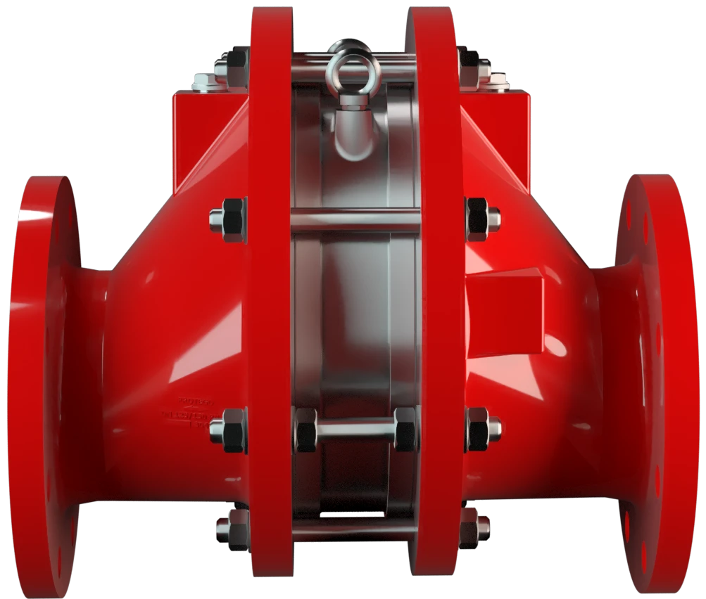
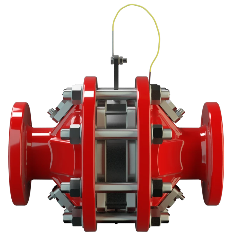
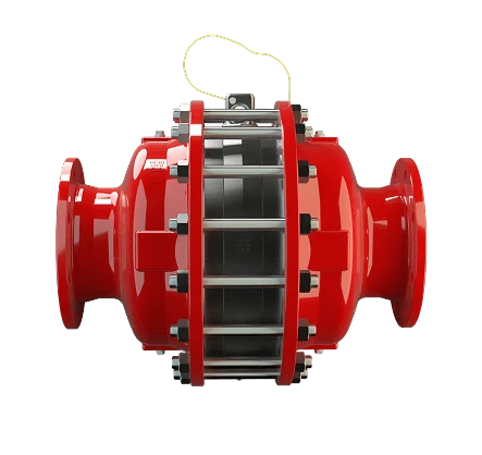
In-line devices
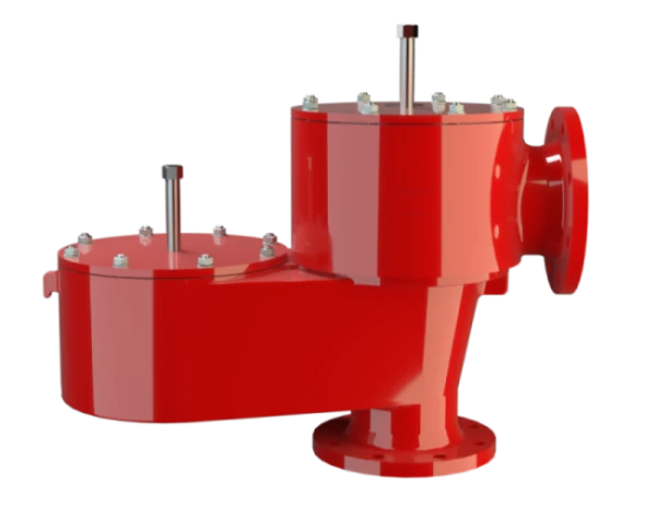
OEM-integrated components
We are highly impressed to see the quality of the products and the knowledge to help us build a state-of-the-art storage terminal. We have always appreciated the timely deliveries of the flame arresters Flame Arresters A flame arrester, deflagration arrester, or flame trap is a device or form of construction that will allow free passage of a gas or gaseous mixture but will interrupt or prevent the passage of flame. and other equipment.


We provide engineered safety solutions.
Since 1954, PROTEGO® has built and provided Flame Arresters Flame arrester Device fitted to the opening of an enclosure, or to the connecting pipe work of a system of enclosures, and whose intended function is to allow flow but prevent the transmission of a flame. , Pressure and Vacuum Relief Valves and Tank Equipment, now with the help of more than 750 employees worldwide.

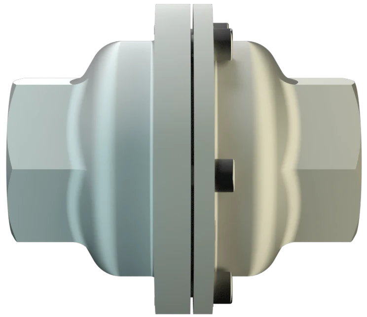
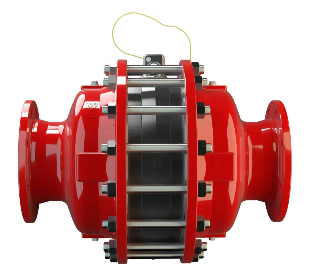
When a flame front enters the arrester, it passes through the FLAMEFILTER® discs. The narrow gaps create a large heat transfer surface, removing energy from the flame faster than combustion can be sustained. The flame is extinguished within the element.
How It Works
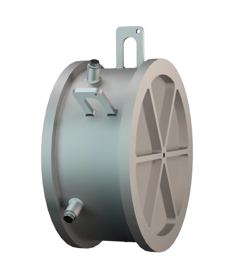
Element Design
The design of the element is not fixed. It is selected based on:
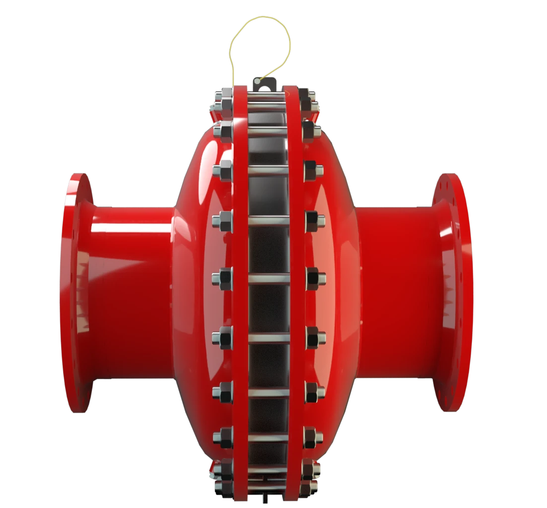
Key Features and Design Characteristics
The element can be removed and serviced without replacing the entire unit, reducing maintenance Maintenance Combination of all technical and administrative actions, including supervision actions, intended to maintain or restore a unit in working order. effort and downtime.
Available in concentric, eccentric, and easy-access designs. Easy-access versions allow maintenance without disconnecting pipework- important in space-constrained or high-uptime environments.
Element gap size is matched to the gas classification (MESG). Correct selection is critical to ensure effective flame arresting.
Options are available depending on whether flow direction is fixed or variable.
Designs are available for substances that may polymerise or crystallise, helping maintain long-term performance.
Heating jackets or coils can be added where condensation or solidification is a risk.
Where standard devices are not suitable, PROTEGO® can design and certify application-specific solutions.
For in-line installations, it is important to understand that protection is time-limited. If an ignitable mixture continues to flow after a flame is stopped, a fire can develop on the arrester itself. For this reason, systems must include:
- Temperature monitoring at the arrester
- A defined response, such as nitrogen purging
OEM-integrated Flame Arresters are tested and approved as part of the equipment assembly and are not used as standalone devices.
Engineering and Compliance
PROTEGO® Deflagration Flame Arresters are type-tested and certified according to ATEX and other international standards. Each device Device A device is a pipe component that influences the media flow by opening, closing, or partially shutting off the flow channel or by dividing or mixing the media flow. is supplied with a statement of conformity defining its approved operating conditions.
Additional installation considerations include:
Sizing is based on the relationship between flow rate and pressure drop using the p/V performance diagram.
Sizing is based on the relationship between flow rate and pressure drop using the p/V performance diagram.
Operational Benefits
Validated protection for OEM equipment
Flexibility for complex applications
Lower maintenance impact
Protection of equipment
Your current location:
Local


Sascha Pineda
Ciprian Dragan
Regy Daniel
Iñigo Velasco Pérez
Regional Sales Manager South America (loctaed at the HQ in Germany)
+49 5307809376
Dr. Jochen Landes
Martyn Killingbeck
Nirmal Rampersad
Maik Mannel

Christian McDonald
Tyson Riggs
Wander Severino Silva
Roberto Moura
Vicente Moura
QuEST Support Team

Nivaldo Júlio Barbosa
Márcio Dobel
Luiz Fernando Falcoski
André Gomes
Dietmar Norz
Jens Ludewig
Armando Espinosa
Joaquín Plaza
Benjamín Plaza Llorente
Tom Sloan
Bojan Rojc
Allan Gaziola
Steven Tan


Carlos Alva

André Plagemann
Xavier Marcús
Johann Kolberger
Erwin Jakob
Jens Planitzer
Volker Haag
TEC-Kundencenter