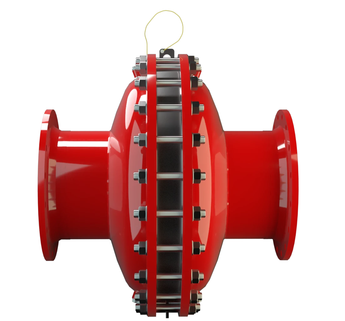
FA-I
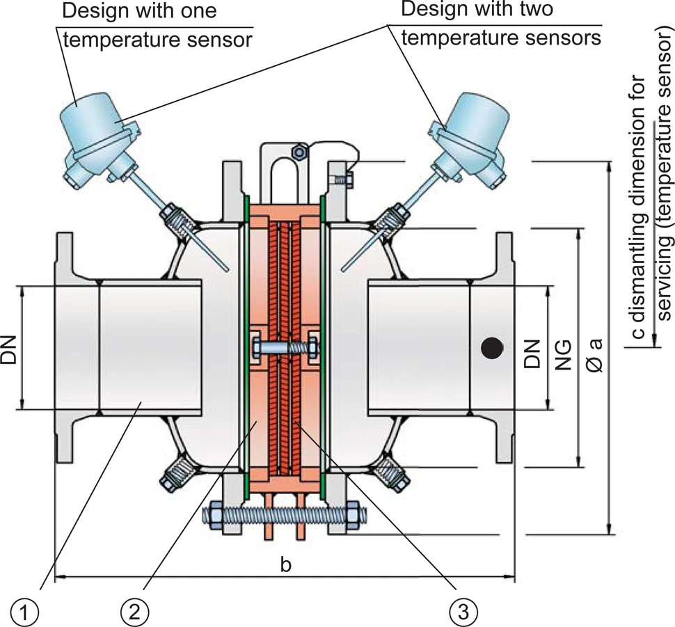
In-Line Deflagration Flame Arrester concentric design, bidirectional
Features
Flow Capacity
Differnt Series
Low Costs
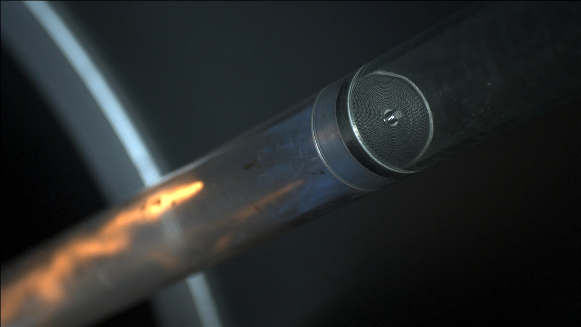
Integrated Cleaning Nozzles
Modular Design
Bi-Directional Flame Transmission
Provides Safety
Extended Application Range
Large Sizes
Spare Parts
Efficient Flow Performance

Main Component – PROTEGO® Flame Arrester Unit
For Explosion Groups IIA to IIB3

Many Individual Certifications
Dimensions
To select nominal width/ nominal size Nominal size The nominal size is an alphanumeric designation of size for components in a piping system, used for reference purposes, comprising the letters DN followed by a dimensionless integer that is indirectly related to the physical size of the bore or outside diameter of the connections, expessed in millimeters. (NG/DN) - combination, please use the flow capacity charts on the following pages. Additional nominal width/nominal size (NG/DN) - combinations for improved flow capacity upon request
| standard | |||||||||||||
| NG | 150 / 6" | 150 / 6" | 200 / 8" | 300 / 12" | 400 / 16" | 500 / 20" | 600 / 24" | 800 / 32" | 1000 / 40" | 1200 / 48" | 1400 / 56" | 1600 / 64 | |
| DN | ≤50 / 2" | 80 / 3" | ≤100 / 4" | ≤150 / 6" | ≤200 / 8" | ≤250 / 10" | ≤300 / 12" | ≤400 / 16" | ≤ 00 / 20" | ≤600 / 24" | ≤800 / 32" | ≤800 / 32" | |
| a | 285 / 11.22 | 285 / 11.22 | 340 / 13.39 | 445 / 17.52 | 565 / 22.24 | 670 / 26.38 | 780 / 30.71 | 975 / 38.39 | 1175 / 46.26 | 1405 / 55.31 | 1630 / 64.17 | 1830 / 72.05 | |
| Expl. Gr. | IIA b* | 364 / 14.33 | 364 / 14.33 | 452 / 17.79 | 584 / 22.99 | 638 / 25.12 | 688 / 27.09 | 800 / 31.50 | 900 / 35.43 | 1000 / 39.37 | 1100 / 43.31 | 1350 / 53.15 | 1450 / 57.09 |
| IIB3 b* | 364 / 14.33 | 364 / 14.33 | 464 / 18.27 | 596 / 23.46 | 650 / 25.59 | 700 / 31.50 | 800 / 31.50 | 900 / 35.43 | 1000 / 39.37 | 1100 / 43.31 | 1350 / 53.15 | 1450 / 57.09 | |
| c | 500 / 19.69 | 500 / 19.69 | 520 / 20.47 | 570 / 22.44 | 620 / 24.41 | 670 / 26.38 | 700 / 31.50 | 900 / 35.43 | 1000 / 39.37 | 1100 / 43.31 | 1350 / 53.15 | 1450 / 57.09 |
Dimensions in mm / inches
*Dimensions b only for P1.2 (IIA) and P1.1 (IIB3)
Selection of explosion group
| MESG | Expl. Gr. (IEC / CEN) | Gas Group (NEC) |
| > 0,90 mm | IIA | D |
| ≥ 0,65 mm | IIB3 | C |
Special approvals upon request
Selection of max. operating pressure
| Expl. Gr. | NG | 150 / 6'' | 150 / 6'' | 200 / 8'' | 300 / 12'' | 400 / 16'' | 500 / 20'' | 600 / 24'' | 800 / 32'' | 1000 / 40'' | 1200 / 48'' | 1400 / 56' | 1600 / 64'' |
| DN | 50 / 1" | 80 / 3" | 100 / 4" | 150 / 6" | 200 / 8" | 250 / 10" | 300 / 12" | 400 / 16" | 500 / 20" | 600 / 24" | 800 / 32" | 800 / 32" | |
| IIA | Pmax | 1,8 / 26.1 | 1,8 / 26.1 | 1,5 / 21.7 | 1,5 / 21.7 | 1,5 / 21.7 | 1,5 / 21.7 | 1,5 / 21.7 | 1,4 / 20.3 | 1,3 / 18.8 | 1,3 / 18.8 | 1,2 / 17.4 | 1,1 / 15.9 |
| IIB3 | Pmax | 1,2 / 17.4 | 1,2 / 17.4 | 1,2 / 17.4 | 1,2 / 17.4 | 1,2 / 17.4 | 1,2 / 17.4 | 1,2 / 17.4 | 1,2 / 17.4 | 1,2 / 17.4 | 1,1 / 15.9 | 1,1 / 15.9 | 1,1 / 15.9 |
Pmax = maximum allowable operating pressure in bar / psi absolute, higher operating pressure upon request
Max. allowable L/D-ratio
| standard | NG | 150 / 6" | 150 / 6" | 200 / 8'' | 300 / 12'' | 400 / 16'' | 500 / 20'' | 600 / 24'' | 800 / 32" | 1000 / 40'' | 1200 / 48'' | 1400 / 56'' | 1600 / 64'' |
| DN | 50 / 1" | 80 / 3" | 100 / 4" | 150 / 6" | 200 / 8" | 250 / 10" | 300 / | 400 / 16" | 500 / 20" | 600 / 24" | 800 / 32" | 800 / 32" | |
| IIA | (L / D)max | 50 | 50 | 50 | 50 | 50 | 50 | 50 | 50 | 50 | 50 | 50 | 50 |
| IIA | Pmax | 1,2 / 17.4 | 1,2 / 17.4 | 1,2 / 17.4 | 1,2 / 17.4 | 1,2 / 17.4 | 1,2 / 17.4 | 1,2 / 17.4 | 1,2 / 17.4 | 1,3 / 18.8 | 1,3 / 18.8 | 1,2 / 17.4 | 1,1 / 15.9 |
| IIA | Designation | - | - | - | - | - | - | - | - | - | - | - | |
| IIB3 | (L / D)max | 50 | 50 | 40 | 40 | 35 | 35 | 35 | 30 | 30 | 30 | 25 | 25 |
| IIB3 | Pmax | 1,1 / 15.9 | 1,1 / 15.9 | 1,1 / 15.9 | 1,1 / 15.9 | 1,1 / 15.9 | 1,1 / 15.9 | 1,1 / 15.9 | 1,1 / 15.9 | 1,1 / 15.9 | 1,1 / 15.9 | 1,1 / 15.9 | 1,1 / 15.9 |
| IIB3 | Designation | - | - | X6 | X6 | X7 | X7 | X7 | X8 | X8 | X8 | X9 | X9 |
Specification of max. operating temperature
| ≤ 60°C / 140°F | Tmaximum allowable operating temperature in °C |
| - | Designation |
higher operating temperatures upon request
Material selection for housing
| Design | A | B | C |
| Housing | Steel | Stainless Steel | Hastelloy |
| Gasket | PTFE | PTFE | PTFE |
| Flame arrester unit Flame arrester unit Flame arrester casing with FLAMEFILTER® set. | A, B | C | D |
The housing can also be delivered in carbon steel with an ECTFE coating Coating Coating is the application of a firmly adhering layer of shapeless material to the surface of a workpiece. . Special materials upon request.
Material combinations of flame arrester unit
| Design | A | C | D |
| FLAMEFILTER® cage | Steel | Stainless Steel | Hastelloy |
| FLAMEFILTER®* | Stainless Steel | Stainless Steel | Hastelloy |
| Spacers | Stainless Steel | Stainless Steel | Hastelloy |
* the FLAMEFILTER® is also available in the materials Tantalum, Inconel, Copper, etc. when the listed housing and cage materials are used
Special materials upon request.
Flange connection type
| EN 1092-1; Form B1 |
| ASME B16.5 CL 150 R.F. |
other connections upon request
Flow Capacity Chart
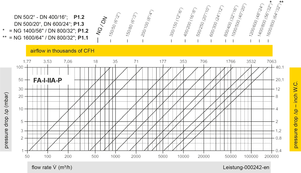
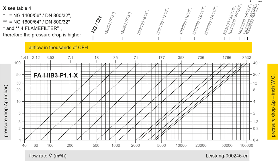
The flow capacity charts have been determined with a calibrated and TÜV certified flow capacity test rig. Volume flow V in (m³/h) and CFH refer to the standard reference conditions of air ISO 6358 (20°C, 1bar). For conversion to other densities and temperatures refer to Sec. 1: “Technical Fundamentals”.


Contact CSR Department
