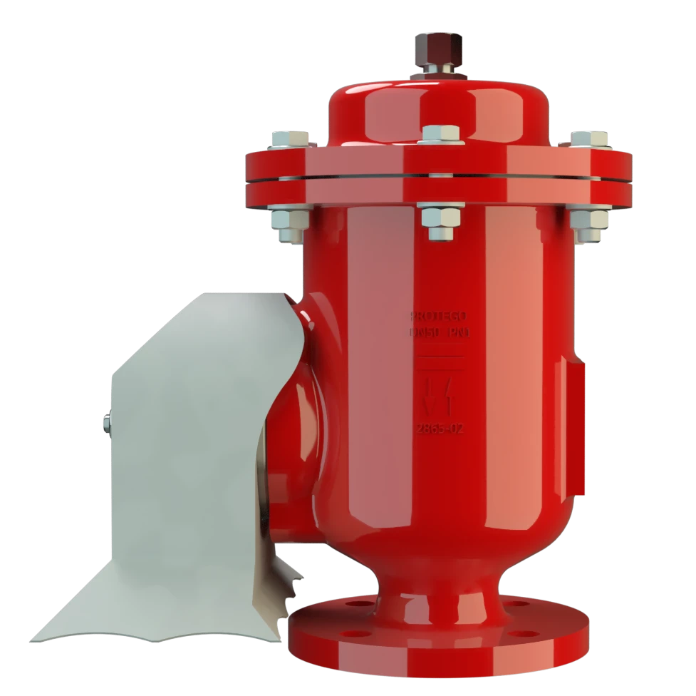
VD/TS
Pressure/Vacuum Relief Valve atmospheric deflagration-proof
Features
10% Technology
Extreme Tightness
Optimum Pressure Maintenance
Guided Valve Pallet
Protective System According to ATEX
Intergrated Flame Arrester
Flow Capacity
Sturdy Housing Design
API Tanks
Combined Pressure and Vacuum Relief Valve

10%-Technology
Custom Materials

Main Component – PROTEGO® Flame Arrester Unit
Dimensions
To select the nominal size Dimensão nominal The nominal size is an alphanumeric designation of size for components in a piping system, used for reference purposes, comprising the letters DN followed by a dimensionless integer that is indirectly related to the physical size of the bore or outside diameter of the connections, expessed in millimeters. (DN), please use the flow capacity charts on the following pages
| DN | 50 / 2" | 80 / 3" | 100 / 4" | 125 / 5" | 150 / 6" | 200 / 8" | 250 / 10" | 300 / 12" |
| a | 340 / 13.39 | 430 / 16.93 | 490 / 19.29 | 610 / 24.02 | 610 / 24.02 | 705 / 27.76 | 765 / 30.12 | 930 / 36.61 |
| b | 210 / 8.27 | 280 / 11.02 | 310 / 12.20 | 390 / 15.35 | 390 / 15.35 | 445 / 17.52 | 505 / 19.88 | 560 / 22.05 |
| c | 206 / 8.11 | 277 / 10.91 | 347 / 13.66 | 427 / 16.81 | 427 / 16.81 | 534 / 21.02 | 604 / 23.78 | 823 / 32.40 |
| d | 125 / 4.92 | 150 / 5.91 | 180 / 7.09 | 230 / 9.06 | 230 / 9.06 | 270 / 10.63 | 310 / 12.20 | 445 / 17.52 |
Dimensions in mm / inches
Selection of explosion group
| MESG | Expl. Gr. (IEC / CEN) | Gas Group (NEC) |
| ≥ 0,65 mm | IIB3 | C |
Special approvals upon request
Specification of max. operating temperature
| ≤ 60°C / 140°F | Tmaximum allowable operating temperature in °C |
| - | Designation |
higher operating temperatures upon request
Material selection for housing
| Design | A | C | D | E | ||
| Housing | Aluminium | Steel | Stainless Steel | Hastelloy | ||
| Valve seats | Stainless Steel | Stainless Steel | Stainless Steel | Hastelloy | ||
| Gasket | PTFE | PTFE | PTFE | PTFE | ||
| Weather hood |
|
| Stainless Steel | Hastelloy | ||
| Flame arrester unit Flame arrester unit Flame arrester casing with FLAMEFILTER® set. | A | A | A | C | ||
| Pressure valve pallet Placa da válvula Valve pallet is the generic term for the assembly that rests on the valve seat. | A-F | A-F | A-F | G-I | ||
| Vacuum valve pallet | A-E | A-E | A-E | F-H |
Special materials upon request
Material combinations of flame arrester unit
| Design | A | C |
| FLAMEFILTER® cage | Stainless Steel | Hastelloy |
| FLAMEFILTER® | Stainless Steel | Hastelloy |
Special materials upon request
Material selection for pressure valve pallet
| Design | A | B | C | D | E | F | G | H | I |
| Pressure range [mbar] [inch W.C.] | +3.5 up to +5,0 +1.4 up to +2.0 | >+5.0 up to +14 >+2.0 up to +5.6 | >+14 up to +35 >+5.6 up to +14 | >+35 up to +50 >+14 up to +20 | >+14 up to +35 >+5.6 up to +14 | >+35 up to +50 >+14 up to +20 | +3.5 up to +5,0 +1.4 up to +2.0 | >+5.0 up to +14 >+2.0 up to +5.6 | >+14 up to +35 >+5.6 up to +14 |
| Valve pallet | Aluminium | Stainless Steel | Stainless Steel | Stainless Steel | Stainless Steel | Stainless Steel | Titanium | Hastelloy | Hastelloy |
| Sealing | FEP | FEP | Metal to Metal | Metal to Metal | PTFE | PTFE | FEP | FEP | Metal to Metal |
| Weight | Stainless Steel | Stainless Steel | Stainless Steel | Lead | Stainless Steel | Lead | Hastelloy | Hastelloy | Hastelloy |
Special material as well as higher set pressure upon request
Material selection for vacuum valve pallet
| Design | A | B | C | E | F | G | H |
| Vacuum range [mbar] [inch W.C.] | -2.0 up to -3.5 -0.8 up to -1.4 | <-3.5 up to -14 <-1.4 up to -5.6 | <-14 up to -25 <-5.6 up to -10 | <-14 up to -25 <-5.6 up to -10 | -2.0 up to -3.5 -0.8 up to -1.4 | <-3.5 up to -14 <-1.4 up to -5.6 | <-14 up to -25 <-5.6 up to -10 |
| Valve pallet | Aluminium | Stainless Steel | Stainless Steel | Stainless Steel | Titanium | Hastelloy | Hastelloy |
| Sealing | FEP | FEP | Metal to Metal | PTFE | FEP | FEP | Metal to Metal |
| Weight | Stainless Steel | Stainless Steel | Stainless Steel | Stainless Steel | Hastelloy | Hastelloy | Hastelloy |
Special material as well as higher set vacuum Vácuo de ajuste Internal negative gauge pressure at which a vacuum valve first opens. upon request
Flange connection type
| EN 1092-1; Form B1 |
| ASME B16.5 CL 150 R.F. |
other types upon request
Flow Capacity Chart
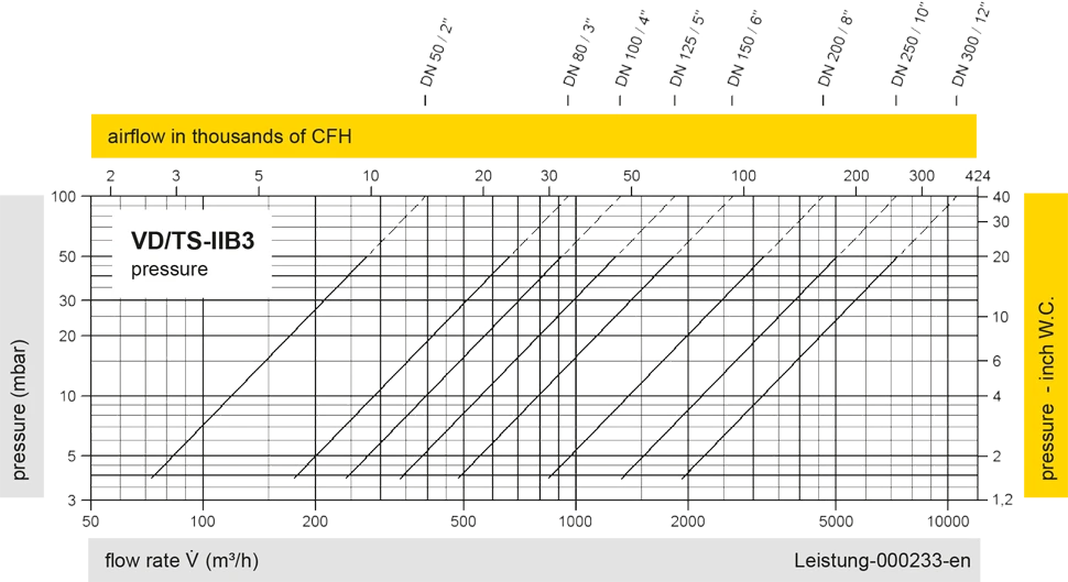
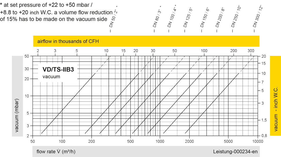
The flow capacity charts have been determined with a calibrated and TÜV certified flow capacity test rig. Volume flow V in (m³/h) and CFH refer to the standard reference conditions of air ISO 6358 (20°C, 1bar). For conversion to other densities and temperatures refer to Sec. 1: “Technical Fundamentals”.
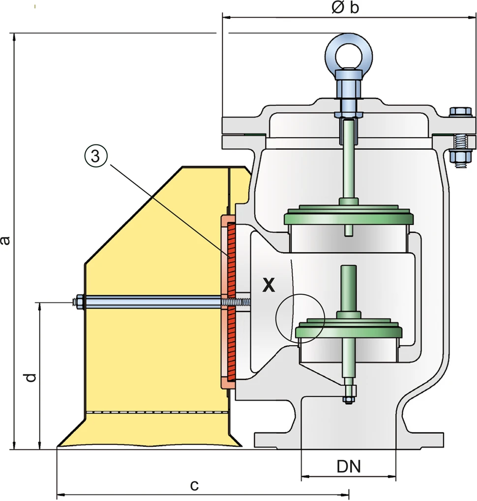

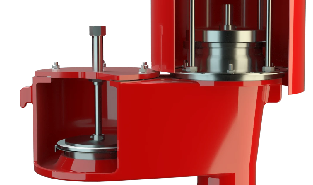
Detail X
Detail X


Contact CSR Department
