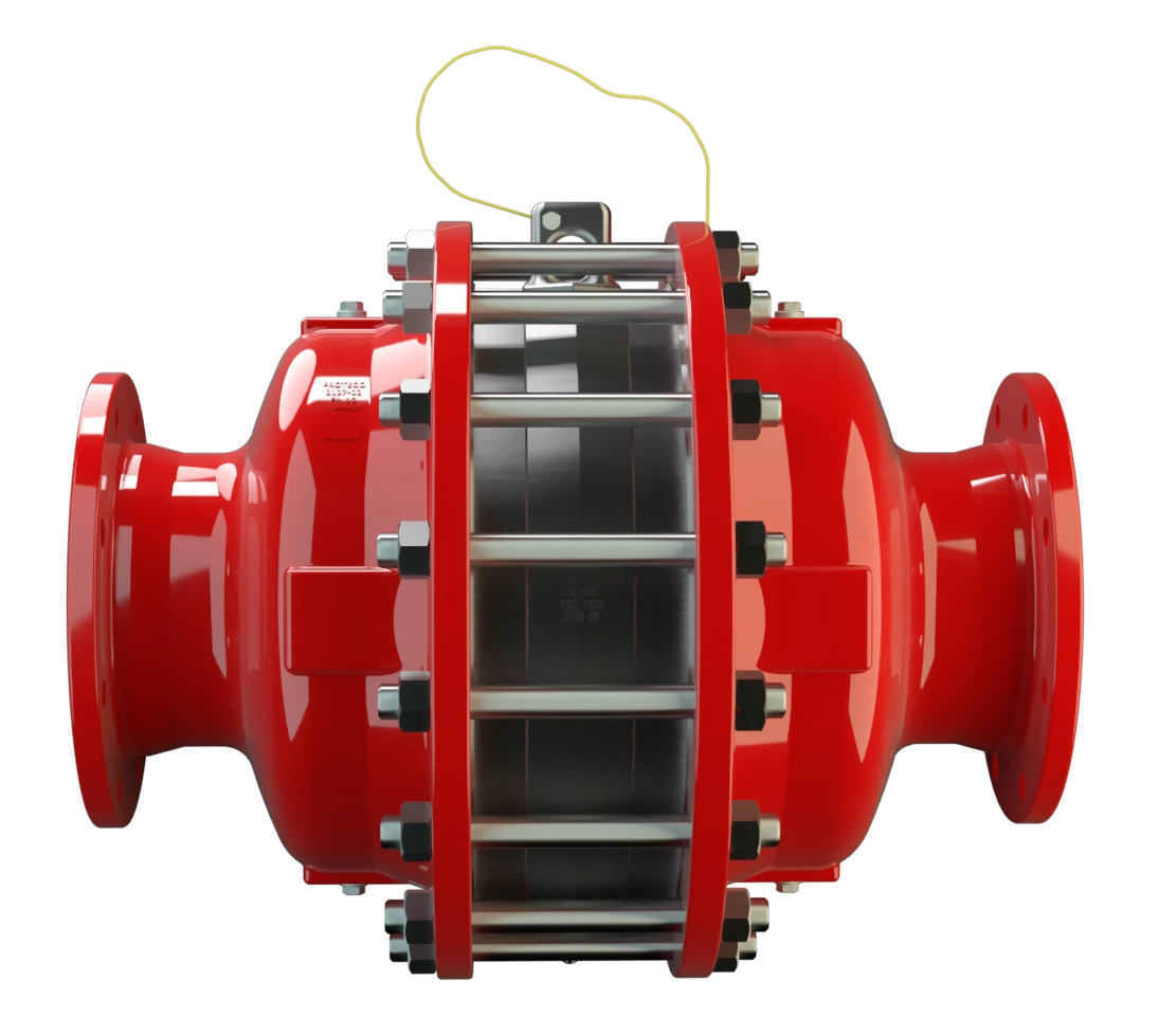
DA-SB
In-Line Detonation Flame Arrester for stable detonations and deflagrations in a straight through design with shock tube, bidirectional
Features
Use of Patented Shock Wave Guide Tube Effect (SWGTE)
Optimized Performance
Extended Application Range
Spare Parts
Low Costs
Maintenance-Friendly PROTEGO® Flame Arresters
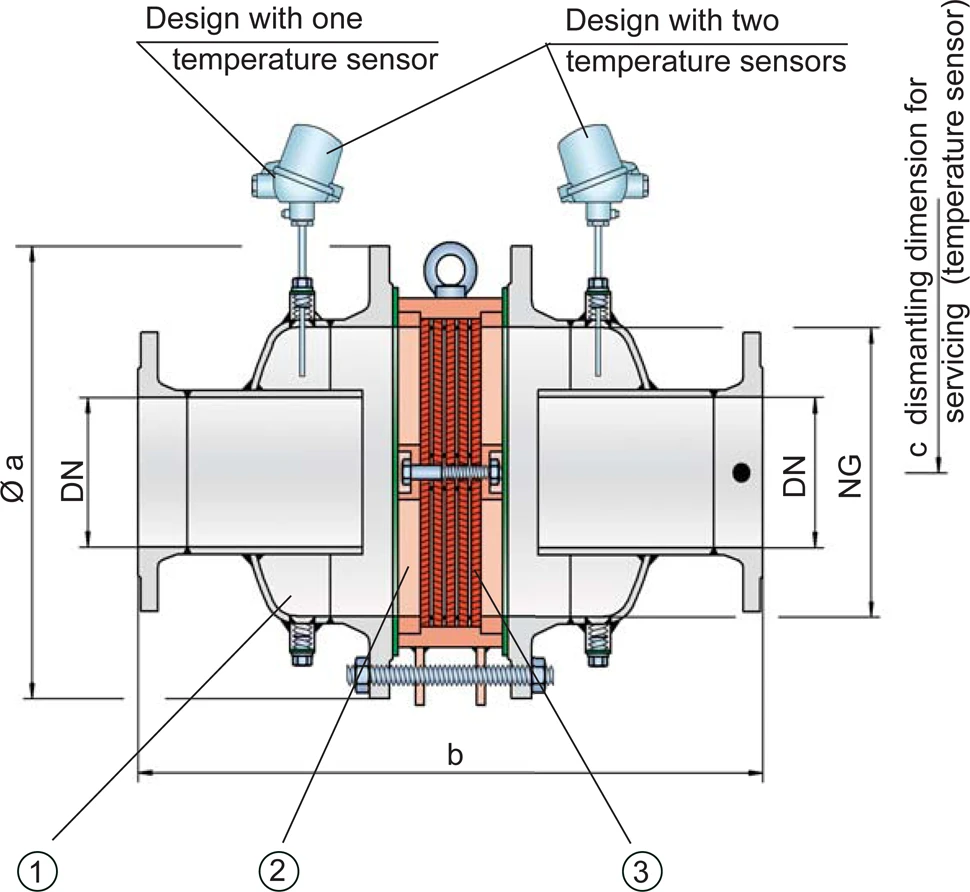
Temperature Sensors Possible
Bi-Directional Flame Transmission
Differnt Series
Minimal Pressure Losses with Maximum Safety

Main Component – PROTEGO® Flame Arrester Unit

Suitable for All Explosion Groups
Dimensions
To select nominal width/
nominal size
Diámetro nominal
The nominal size is an alphanumeric designation of size for components in a piping system, used for reference purposes, comprising the letters DN followed by a dimensionless integer that is indirectly related to the physical size of the bore or outside diameter of the connections, expessed in millimeters.
(NG/DN) - combination, please use the flow capacity charts on the following pages
Additional nominal width/nominal size (NG/DN) - combinations for improved flow capacity upon request
| standard | |||||||||||||
| NG | 150 / 6" | 150 / 6" | 200 / 8" | 300 / 12" | 400 / 16" | 500 / 20" | 600 / 24" | 700 / 28" | 800 / 32" | 1000 / 40" | 1200 / 48" | 1600 / 64" | |
| DN | ≤50 / 2" | 65, 80 / 2½“, 3" | ≤100 / 4" | ≤150 / 6" | ≤200 / 8" | ≤250 / 10" | ≤300 / 12" | ≤350 / 14" | ≤400 / 16" | ≤500 / 20" | ≤600 / 24" | ≤800 / 32" | |
| a | 285 / 11.22 | 285 / 11.22 | 340 / 13.39 | 445 / 17.52 | 565 / 22.24 | 670 / 26.38 | 780 / 30.71 | 895 / 35.24 | 1015 / 39.96 | 1230 / 48.43 | 1455 / 57.28 | 1915 / 75.39 | |
| b | IIA-P1,1 | 388 / 15.28 | 388 / 15.28 | 476 / 18.74 | 626 / 24.65 | 700 / 27.56 | 800 / 31.50* | 1000 / 39.37* | 1200 / 47.24 | 1400 / 55.12 | 1600 / 62.99 | 1800 / 70.87 | 2200 / 86.61** |
| IIA-P1,4-X3 | 400 / 15.75 | 400 / 15.75 | 488 / 19.21 | 626 / 24.65 | 700 / 27.56 | 800 / 31.50 | 1000 / 39.37 | 1200 / 47.24 | 1400 / 55.12 | ||||
| IIB3-P1,1 | 400 / 15.75 | 412 / 16.22 | 500 / 19.69 | 650 / 25.59 | 724 / 28.50 | 824 / 32.44 | 1000 / 39.37 | 1200 / 47.24 | 1400 / 55.12 | 1600 / 62.99 | 1800 / 70.87 | ||
| IIB3-P1,4-X3 | 412 / 16.22 | 412 / 16.22 | 512 / 20.16 | 650 / 25.59 | 724 / 28.50 | 824 / 32.44 | 1000 / 39.37 | 1200 / 47.24 | 1400 / 55.12 | ||||
| IIC-P1,1 | 400 / 15.75 | 400 / 15.75 | 500 / 19.69 | 638 / 25.12 | 700 / 27.56 | 788 / 31.02 | 1000 / 39.37*** | 1200 / 47.24*** | 1400 / 55.12*** | ||||
| c | 500 / 19.69 | 500 / 19.69 | 520 / 20.47 | 570 / 22.44 | 620 / 24.41 | 670 / 26.38 | 720 / 28.35 | 770 / 30.31 | 820 / 32.28 | 950 / 37.40 | 1050 / 41.34 | 1250 / 49.21 |
Dimensions in mm / inches
special sizes up to NG 2000/80“, DN 1000/40“ available
* dimension b only for P1.4 / 20.3
** dimension b only for P1.2 / 17.4
*** EN 12874
Selection of explosion group
| MESG | Expl. Gr. (IEC / CEN) | Gas Group (NEC) |
| > 0,90 mm | IIA | D |
| ≥ 0,65 mm | IIB3 | C |
| < 0,50 mm | IIC | B |
Special approvals upon request
Selection of max. operating pressure
| Expl. Gr. | DN | 50 / 2" | 80 / 3" | 100 / 4" | 150 / 6" | 200 / 8" | 250 / 10" | 300 / 12 " | 350 / 14" | 400 / 16" | 500 / 20'' | 600 / 24" | 800 / 32" |
| NG | 150 / 6'' | 150 / 6'' | 200 / 8'' | 300 / 12'' | 400 / 16'' | 500 / 20'' | 600 / 24'' | 700 / 28'' | 800 / 32'' | 1000 / 40'' | 1200 / 48'' | 1600 / 64'' | |
| IIA | Pmax | 2,1 / 30.5 | 2,1 / 30.5 | 2,1 / 30.5 | 2,1 / 30.5 | 2,1 / 30.5 | 2,1 / 30.5 | 1,4 / 20.3 | 1,4 / 20.3 | 1,4 / 20.3 | 1,1 / 15.9 | 1,1 / 15.9 | 1,2 / 17.4 |
| IIB3 | Pmax | 1,4 / 20.3 | 1,4 / 20.3 | 1,4 / 20.3 | 1,8 / 26.1 | 1,8 / 26.1 | 1,8 / 26.1 | 1,8 / 26.1 | 1,4 / 20.3 | 1,4 / 20.3 | 1,1 / 15.9 | 1,1 / 15.9 | - |
| IIC | Pmax | 2,2 / 31.9 | 2,2 / 31.9 | 1,1 / 15.9 | 1,1 / 15.9 | 1,1 / 15.9 | 1,1 / 15.9 | 1,1* / 15.9 | 1,1* / 15.9 | 1,1* / 15.9 | - | - | - |
Pmax = maximum allowable operating pressure in bar / psi absolut, higher operating pressure upon request
in-between size up to Pmax upon request
*capacity charts upon request
Specification of max. operating temperature
| ≤ 60°C / 140°F | ≤ 200°C / 392°F | Tmaximum allowable operating temperature in °C |
| - | X3 | Designation |
higher operating temperatures upon request
Material selection for housing
| Design | A | B | C |
| Housing | Steel | Stainless Steel | Hastelloy |
| Heating jacket (DA-SB-(T)-H-...) | Steel | Stainless Steel | Stainless Steel |
| Gasket | PTFE | PTFE | PTFE |
| Flame arrester unit Flame arrester unit Flame arrester casing with FLAMEFILTER® set. | A, B | B, C, D | D |
The housing is also available in carbon steel with an ECTFE coating Revestimiento Coating is the application of a firmly adhering layer of shapeless material to the surface of a workpiece. .
Special materials upon request
Material combinations of flame arrester unit
| Design | A | B | C | D |
| FLAMEFILTER® cage | Steel | Stainless Steel | Stainless Steel | Hastelloy |
| FLAMEFILTER®* | Stainless Steel | Stainless Steel | Hastelloy | Hastelloy |
| Spacer | Stainless Steel | Stainless Steel | Hastelloy | Hastelloy |
*the FLAMEFILTER® are also available in the materials Tantalum, Inconel, Copper, etc. when the listed housing and cage materials are used.
Special materials upon request
Flange connection type
| EN 1092-1; Form B1 |
| ASME B16.5 CL 150 R.F. |
other connections upon request
Flow Capacity Chart
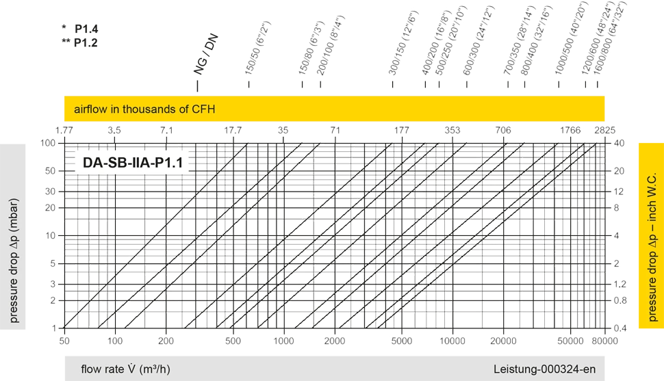
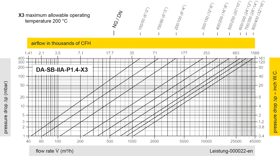
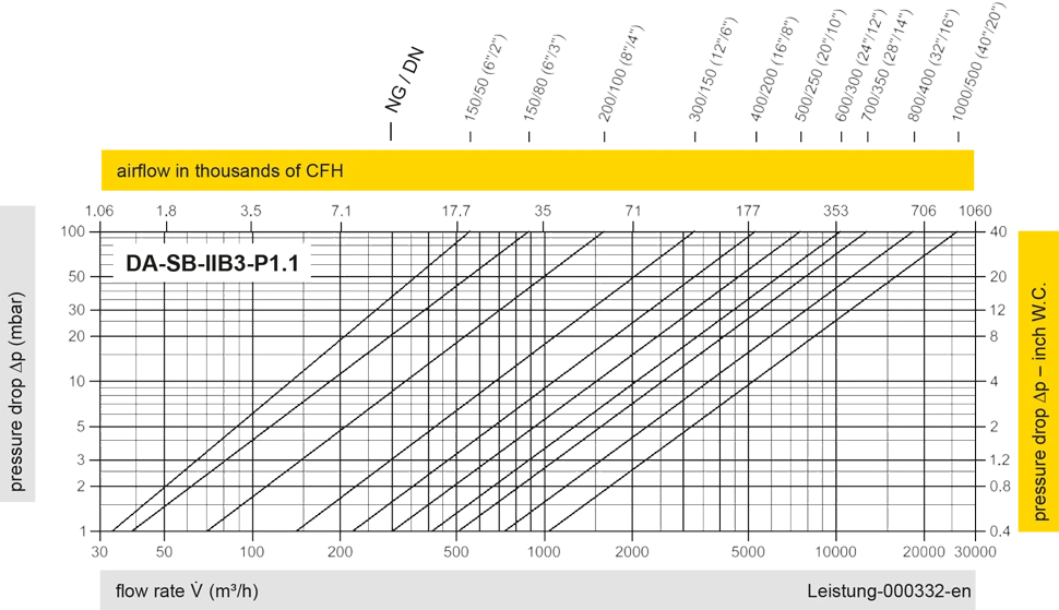
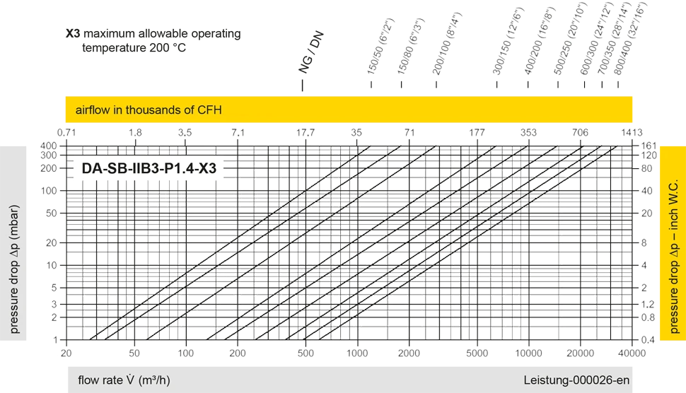
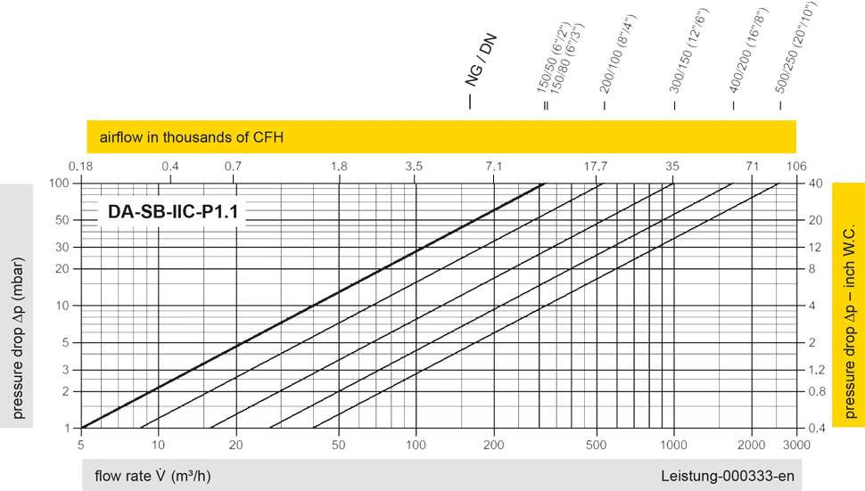
The flow capacity charts have been determined with a calibrated and TÜV certified flow capacity test rig. Volume flow V in (m³/h) and CFH refer to the standard reference conditions of air ISO 6358 (20°C, 1bar). For conversion to other densities and temperatures refer to Sec. 1: “Technical Fundamentals”.


Si vous avez des questions, des commentaires ou des suggestions, notre équipe d'experts se fera un plaisir de vous aider.
