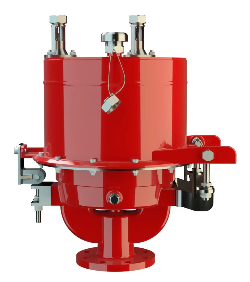
UB/SF
Pressure/Vacuum Diaphragm Valve deflagration- and endurance burning-proof
Features
Extreme Tightness
Optimal Pressure Maintenance
Flow Capacity
Digital Level Monitoring
Digital Level Sensors
Safe Venting
Frost-Proof
Condensate Drainage
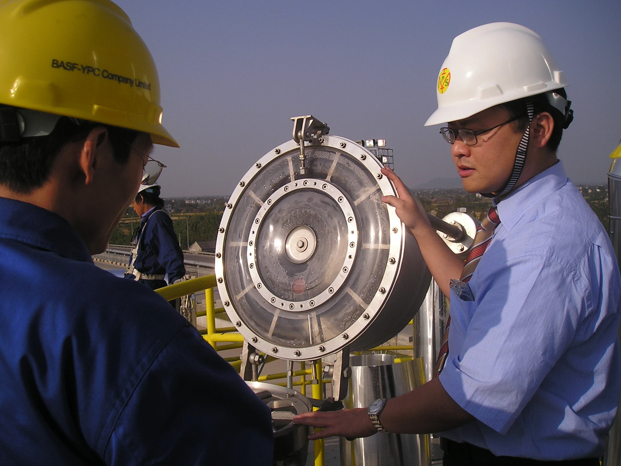
Monitoring
Modular Design
Suitable for Challenging Applications
Easy Operation Monitoring
Protective System According to ATEX
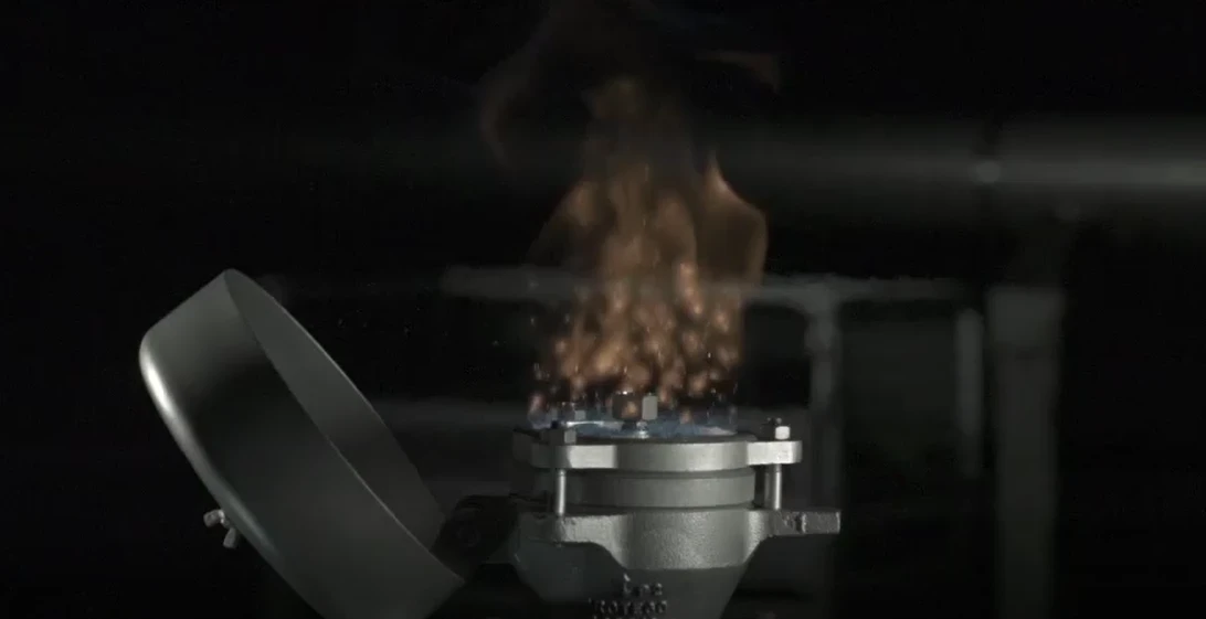
Safety Against Endurance Burning
Combined Pressure and Vacuum Relief Valve
For Explosion Group IIB3
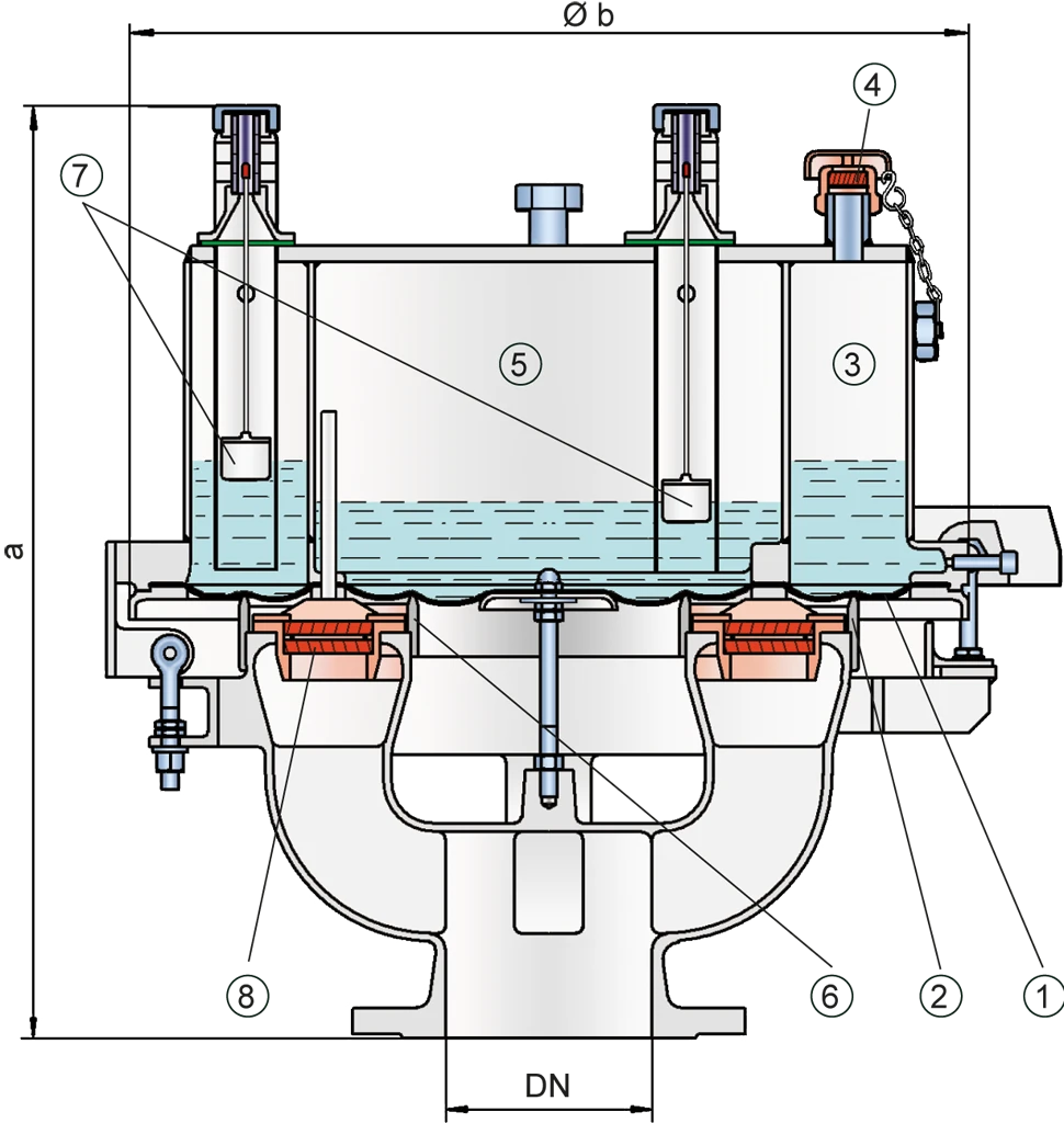
Composition
Advanced Manufacturing Technology
Dynamic Flame Arresting Under Overpressure Conditions
Main Component – PROTEGO® Flame Arrester Unit
Dimensiones
To select the nominal size Diámetro nominal The nominal size is an alphanumeric designation of size for components in a piping system, used for reference purposes, comprising the letters DN followed by a dimensionless integer that is indirectly related to the physical size of the bore or outside diameter of the connections, expessed in millimeters. (DN), please use the flow capacity charts on the following pages
| DN | pressure | pressure | 80 / 3" | pressure | pressure | 100 / 4" | pressure | pressure | 150 / 6" |
| a | up to +28 mbar | up to +11.2 inch W.C. | 615 / 24.21 | up to +28 mbar | up to +11.2 inch W.C. | 645 / 25.39 | up to +25 mbar | up to +10 inch W.C. | 680 / 26.77 |
| a | > +28 mbar | > +11.2 inch W.C. | 765 / 30.12 | > +28 mbar | > +11.2 inch W.C. | 795 / 31.30 | > +25 mbar | > +10 inch W.C. | 830 / 32.68 |
| b | 410 / 16.14 | 485 / 19.09 | 590 / 23.23 |
Dimensiones en mm / pulgadas
Pressure settings > +50 mbar / +20 inch W.C. (DN 80/3”), > +45 mbar / +18 inch W.C. (DN 100/4”), > +46 mbar / +18.4 inch W.C. (DN150/6”) with additional liquid reservoir - dimensions upon request
Dimensions for pressure/vacuum diaphragm valves with heating coil Serpentín de calefacción A heating coil is a pipe connection consisting of several pipe sections. upon request
Selección del grupo de explosión
| MESG | Expl. Gr. (IEC / CEN) | Gas Group (NEC) |
| ≥ 0,65 mm | IIB3 | C |
Special approvals upon request
Selección de materiales para la vivienda
| Design | C | D |
| Housing | Steel | Stainless Steel |
| Valve top | Stainless Steel | Stainless Steel |
| Heating coil (UB / SF-H-...) | Stainless Steel | Stainless Steel |
| Valve seat | Stainless Steel | Stainless Steel |
| Gasket | FPM | PTFE |
| Diaphragm | A, B | A, B |
| Flame arrester unit Flame arrester unit Flame arrester casing with FLAMEFILTER® set. | C | C |
Option: Housing with ECTFE- lining Lining Protective plastic lining with a defined minimum/maximum thickness to protect against aggressive mixtures (e.g., acid).
Special materials upon request
Selección de materiales
| Design | A | B |
| Diaphragm | FPM | FEP |
Special materials upon request
Combinación de materiales para la unidad apagallamas
| Design | C |
| FLAMEFILTER® cage | Stainless Steel |
| FLAMEFILTER® | Stainless Steel |
| Spacer | Stainless Steel |
Special materials upon request
Tipo de bridas de conexión
| EN 1092-1; Form B1 |
| ASME B16.5 CL 150 R.F. |
other types upon request
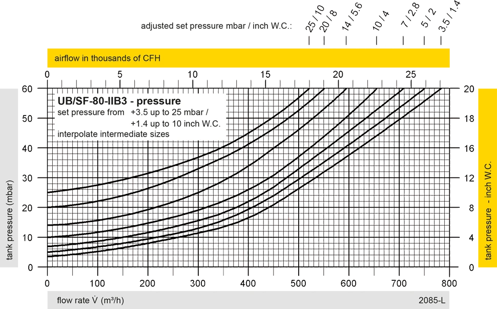
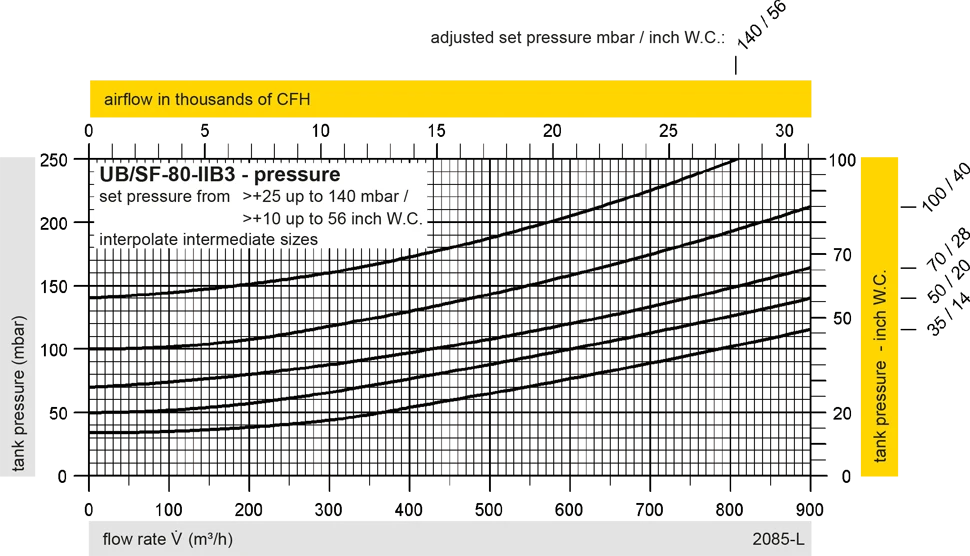
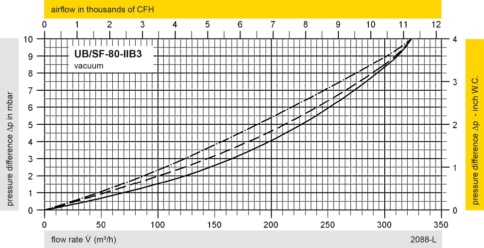
Diagrama de flujo volumétrico
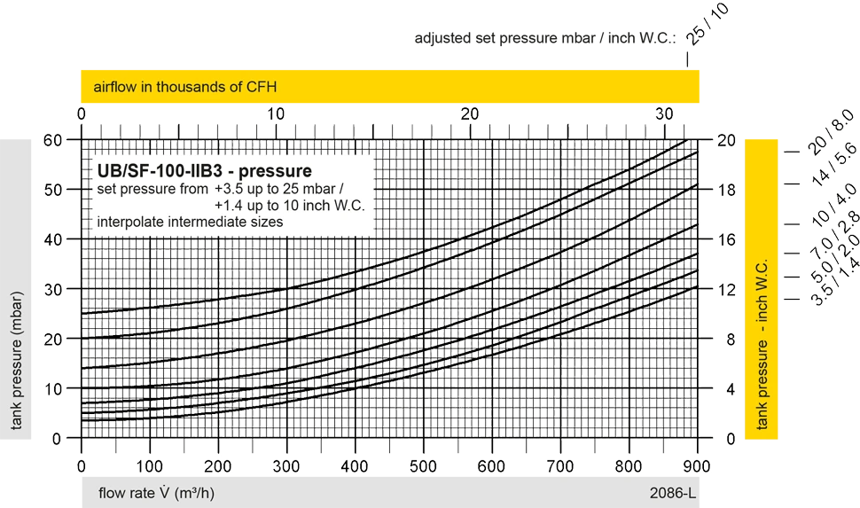
UB/SF DN100 Pressure

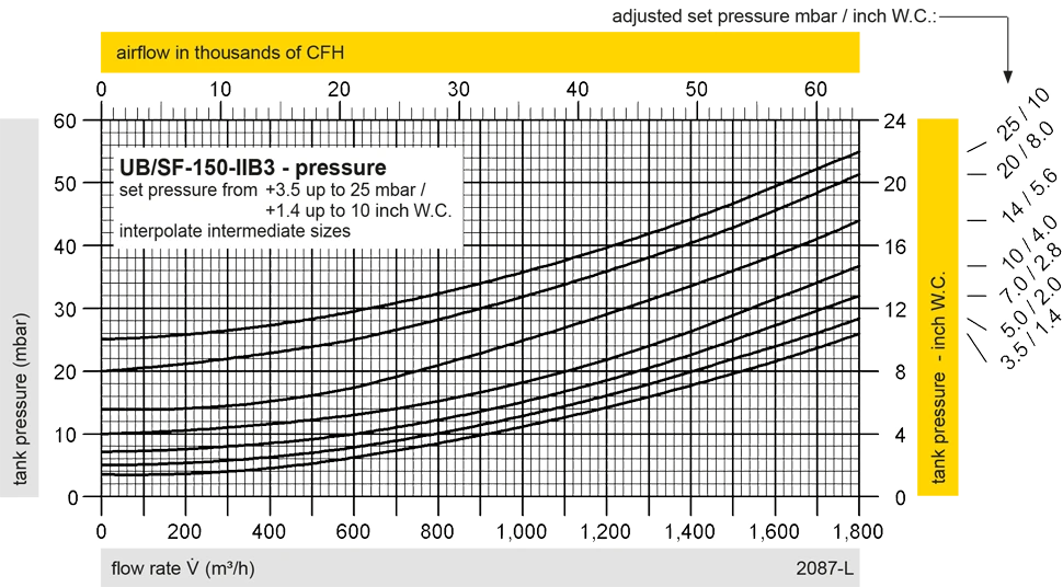
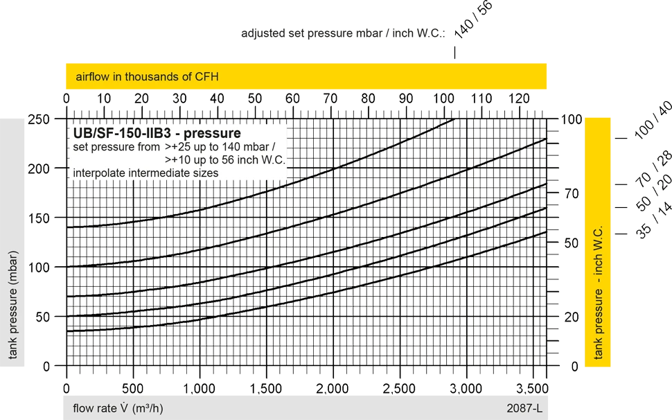
UB/SF DN150 Pressure
UB/SF DN80 Vacuum
UB/SF DN100 Vacuum

UB/SF DN150 Vacuum
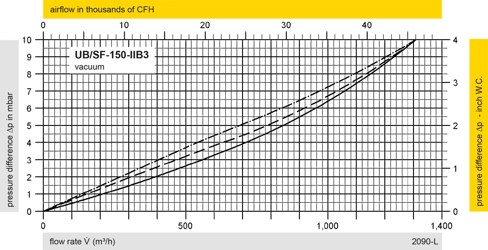
Los diagramas de flujo volumétrico han sido determinados con un banco de pruebas de caudal calibrado y certifi - cado por TÜV. El flujo volumétrico V. en [m³/h] y el CFH se refi eren a las condiciones estándar de referencia de aire según ISO 6358 (20°C, 1bar). La conversión a otras densidades y temperaturas están referidas en el Vol. 1: “Fundamentos Técnicos”.


Si tienes alguna pregunta, comentario o sugerencia, nuestro equipo de expertos estará encantado de ayudarte.
