Features
10% Technology
Extreme Tightness
Optimum Pressure Maintenance
High Flow Capacity
For Over- and Underpressure
Used in Explosion Hazardous Areas
Sturdy Housing Design
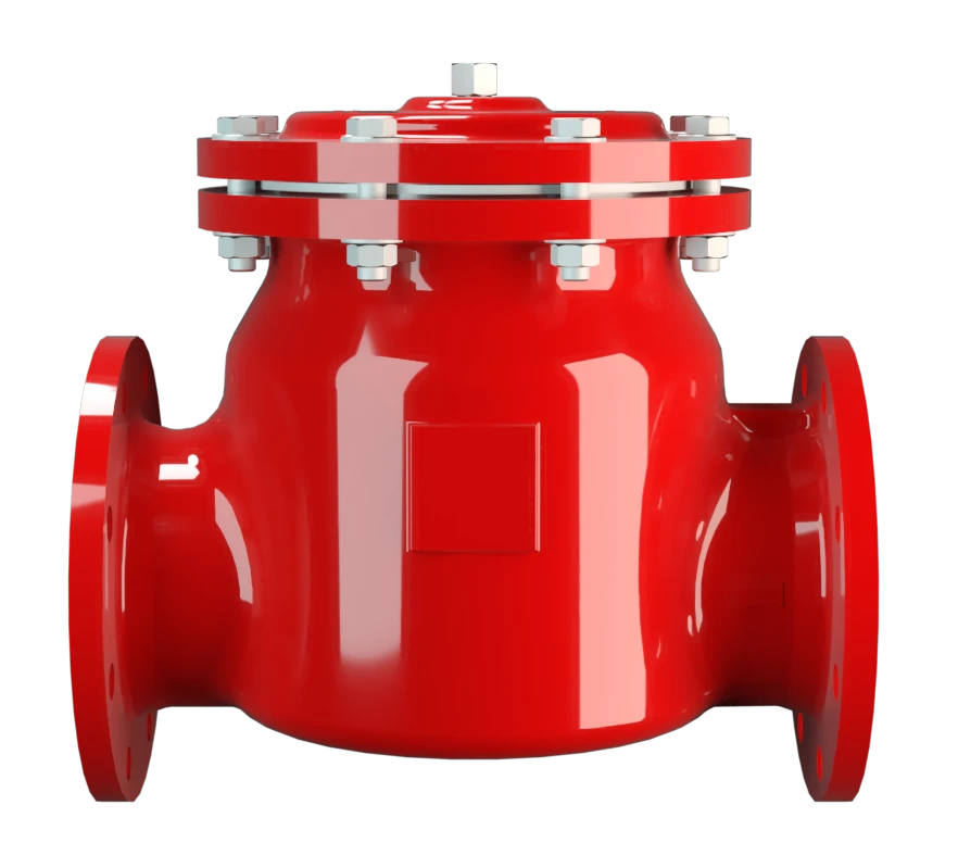
Proteção contra pressão ou refluxo em linhas de ventilação ou exaustão

Tecnologia de curso pleno
Tecnologia avançada de manufatura
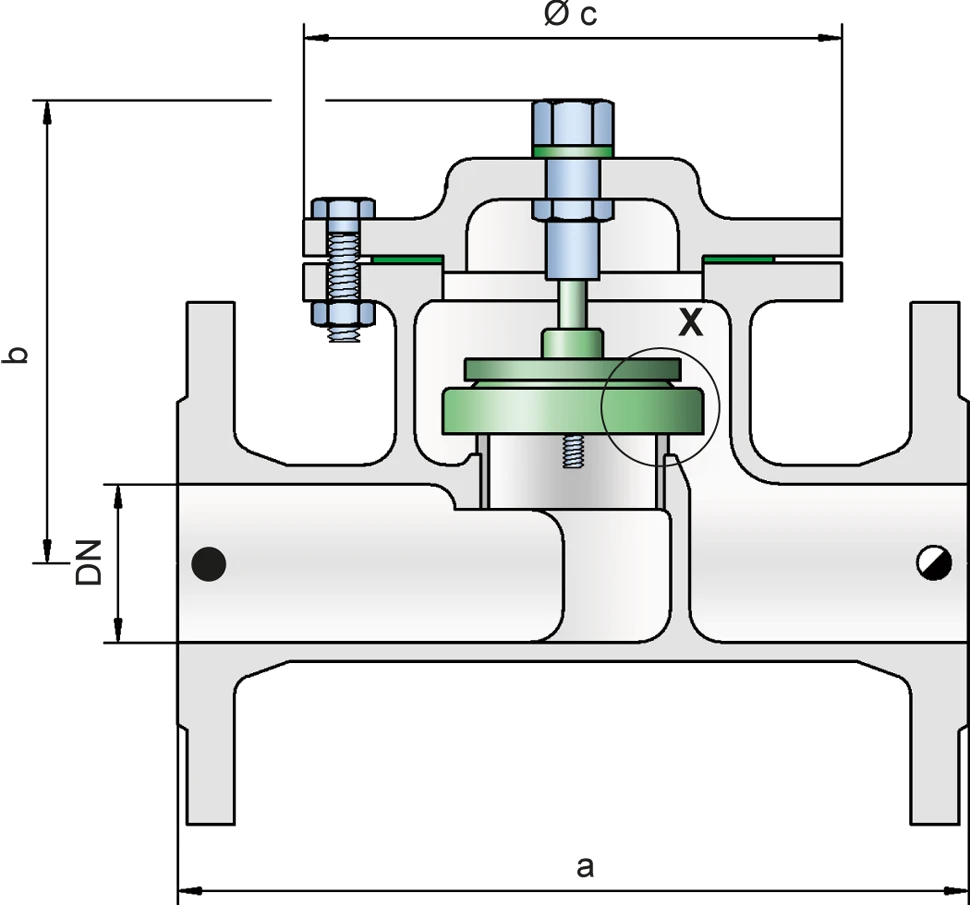
Tabela de dimensões
Para escolher o diâmetro nominal (DN), veja o diagrama de vazão da página seguinte
| DN | 25 / 1" | 32 / 1¼" | 40 / 1½" | 50 / 2" | 65 / 2½" | 80 / 3" | 100 / 4" | 150 / 6" | 200 / 8" | 250 / 10" | 300 / 12" |
| a | 220 | 220 | 250 | 250 | 340 | 340 | 380 | 460 | 550 | 650 | 700 |
| b | 140 | 140 | 190 | 190 | 210 | 210 | 240 | 305 | 460 | 515 | 555 |
| c | 150 | 150 | 170 | 170 | 235 | 235 | 280 | 335 | 420 | 505 | 565 |
Dimensões em mm
Dimensões para a válvula de pressão ou vácuo para tubulação com camisa de aquecimento sob solicitação
Seleção do material do corpo
| Execução | A | B | C |
| Corpo | Aço | Aço inoxidável | Hastelloy |
| Camisa de aquecimento (DZ / T-H-...) | Aço | Aço inoxidável | Aço inoxidável |
| Sede de válvula | Aço inoxidável | Aço inoxidável | Hastelloy |
| Vedação | PTFE | PTFE | PTFE |
| Prato de válvula DN 40 - 300 | A, C, E, F | A, C, E, F | B, D, G |
| Disco de válvula DN 25 - 32 | H, I, J | H, I, J | – |
Os corpos também podem ser fornecidos com revestimento de ECTFE
Materiais especiais sob solicitação
Seleção de material do obturador da válvula
| DN 40-300 | |||||||
| Execução | A | B | C | D | E | F | G |
| Faixa de pressão [mbar] | ±2,0 até ±3,5 | ±2,0 até ±3,5 | ±3,5 até ±14 | ±3,5 até ±14 | ±14 até ±60 | ±14 até ±60 | ±14 até ±60 |
| Disco da válvula | Alumínio | Titânio | Aço inoxidável | Titânio | Aço inoxidável | Aço inoxidável | Hastelloy |
| Vedação | FEP | FEP | FEP | FEP | metálica | PTFE | metálica |
| DN 25-32 | |||||||
| Execução | H | I | J | ||||
| Faixa de pressão [mbar] | ±3,5 até ±15 | ±15 até ±60 | ±15 até ±60 | ||||
| Disco da válvula | PTFE | Aço inoxidável | Aço inoxidável | ||||
| Vedação | PTFE | metálica | PTFE |
Materiais especiais, bem como ajustes de pressão mais altos sob solicitação.
Em caso de ajustes de pressão mais altos, usar o tipo DZ/T-F (também em caso de vácuo maior)
Tipo de conexão flangeada
| EN 1092-1; Form B1 |
| ASME B16.5 CL 150 R.F. |
Outras conexões sob solicitação
Diagrama de vazão
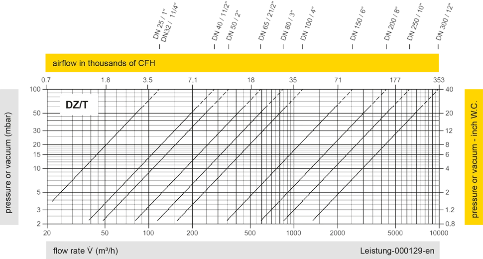
Este diagrama de vazão foi determinado em uma bancada de medição de vazão calibrada e certificada pela TÜV. A vazão V em m³/h se refere ao estado técnico padrão de ar, conforme ISO 6358 (20°C, 1bar). Para conversão em outras densidades e temperaturas, veja o cap. 1: Bases técnicas.
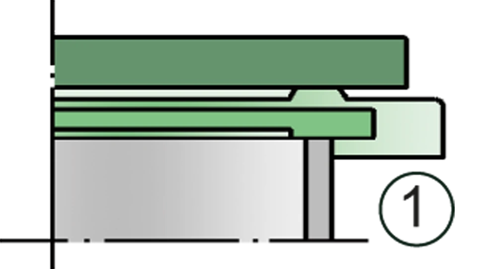
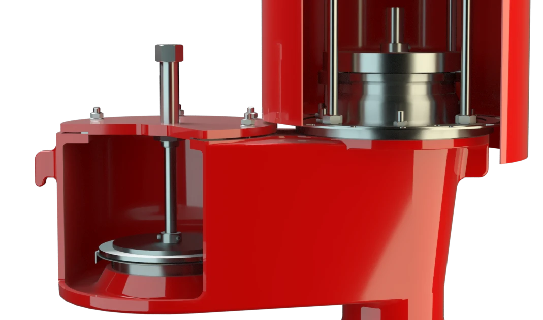
Detalhe X
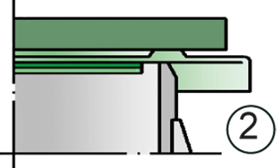
Detalhe X

conexão do tanque na função de alívio de pressão

conexão do tanque na função de alívio de vácuo


Se você tiver alguma dúvida, comentário ou sugestão, nossa equipe de especialistas terá prazer em ajudá-lo.
