BE/HR
Calota de respiro à prova de deflagração e combustão contínua

Features
Comprehensive Weather Protection
Weather Hood With Protection Screen Protects the PROTEGO® Flame Arrester Unit Against Environmental Impact, Such as Nesting Animals and Weather Conditions
Visible Fire Indication by Tilting Weather Hood
in Case of Fire, the Weather Hood Opens, Allowing the Flame to Be Seen From a Far Distance
Safety Against Endurance Burning
Protection against Atmospheric Deflagration and Endurance Burning
Chemically Resistant
Centrally Aligned Melting Element Is Resistant to Chemicals
Modular Design
Allows Replacement and Cleaning of Single FLAMEFILTER®
Spare Parts
Cost-Effective Spare Parts
Function and Description
Proteção contra deflagração atmosférica e queima sustentada
Há vários anos que o corta-chamas do tipo PROTEGO® BE/HR é usado com sucesso para a proteção de instalações e vasos sem pressão. A calota de respiro oferece proteção contra deflagrações atmosféricas e queima estabilizada de longa duração, a chamada combustão contínua. Os equipamentos são instalados preferencialmente em tubos de alívio de pressão e vácuo, impedindo deste modo a entrada de uma combustão ou de uma deflagração atmosférica para o interior de um vaso ou de uma instalação.
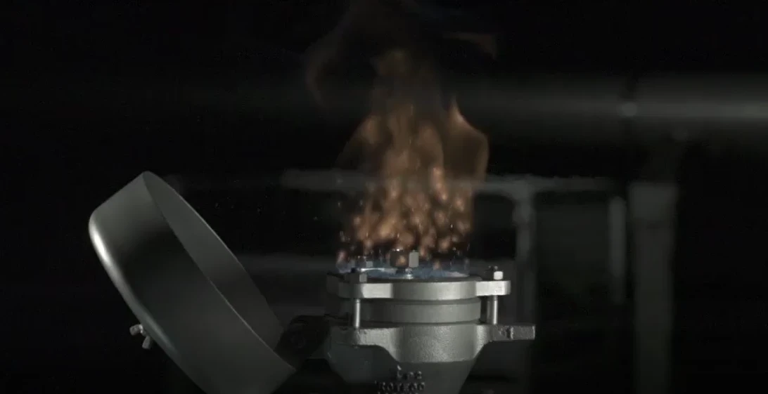
Componente Principal – Conjunto Abafador de Chamas PROTEGO®
O dispositivo do tipo PROTEGO® BE/HR é essencialmente composto de um corpo (1), da tampa (2) e do conjunto abafador de chamas PROTEGO® (3). A calota de respiro é fechada com uma tampa metálica de proteção contra intempéries. Em caso de uma combustão sobre o conjunto abafador de chamas PROTEGO® , o elemento fusível centrado (5) se derrete e a tampa montada com mola abre. Dois FLAMEFILTER® (4), encaixados de forma estável em uma armação do FLAMEFILTER® , caracterizam o conjunto abafador de chamas PROTEGO® . A altura e o espaçamento dos FLAMEFILTER® são adaptados dependendo das condições de uso.

Para os grupos de explosão IIA a IIB3
Dependendo do tipo, os corta-chamas da série PROTEGO® m BE/HR estão disponíveis para substâncias dos grupos de explosão IIA até IIB3. Também estão disponíveis dispositivos à prova de combustão contínua para substâncias especiais, como por exemplo etanol.
A versão padrão pode ser usada até uma temperatura de trabalhomde +60°C.
Teste de protótipo segundo a diretriz ATEX e EN ISO 16852, assim como outras normas internacionais.
Product Data
Tabela de dimensões
Para selecionar o diâmetro nominal (DN), veja os diagramas de vazão nas páginas seguintes
| DN | 80 / 3" | 100 / 4" |
| a | 353 | 353 |
| b | 250 | 250 |
Dimensões em mm
Medidas de montagem para a calota de respiro com camisa de aquecimento sob solicitação
Seleção do grupo de explosão
| MESG | Gr. expl. (IEC / CEN) | Grupo gás (NEC) |
| > 0,90 mm | IIA | D |
| ≥ 0,65 mm | IIB3 | C |
Aprovações especiais sob solicitação
Seleção do material do corpo
| Execução | B | C |
| Corpo | Aço | Aço inoxidável |
| Tampa | Aço | Aço inoxidável |
| Conjunto abafador de chamas | A | A, C |
Materiais especiais sob solicitação
Combinações de material do conjunto abafador de chamas
| Execução | A | C |
| Armação do FLAMEFILTER® | Aço inoxidável | Aço inoxidável |
| FLAMEFILTER® | Aço inoxidável | Hastelloy |
| Espaçador | Aço inoxidável | Hastelloy |
Materiais especiais sob solicitação
Tipo de conexão flangeada
| EN 1092-1; Form B1 |
| ASME B16.5 CL 150 R.F. |
Outras conexões sob solicitação
Diagrama de vazão
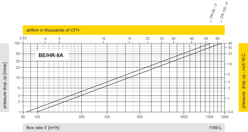
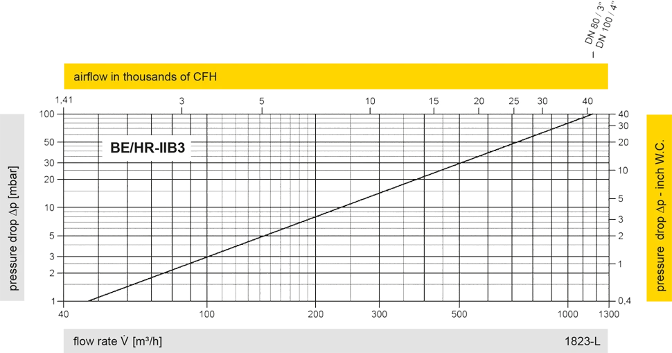
Este diagrama de vazão foi determinado em uma bancada de medição de vazão calibrada e certificada pela TÜV. A vazão V em m³/h se refere ao estado técnico padrão de ar, conforme ISO 6358 (20°C, 1bar). Para conversão em outras densidades e temperaturas, veja o cap. 1: Bases técnicas.


Se você tiver alguma dúvida, comentário ou sugestão, nossa equipe de especialistas terá prazer em ajudá-lo.
