Features
Comprehensive Weather Protection
Weather Hood With Protection Screen Protects the PROTEGO® Flame Arrester Unit Against Environmental Impact, Such as Nesting Animals and Weather Conditions
Various Sizes
Available for DN 50/2"– bis DN 800/32"– Pipes
Extended Application Range
for Elevated Operating Temperatures and Pressures
Spare Parts
Cost-Effective Spare Parts
Low Costs
Low Operating and Lifecycle Costs
Saftey
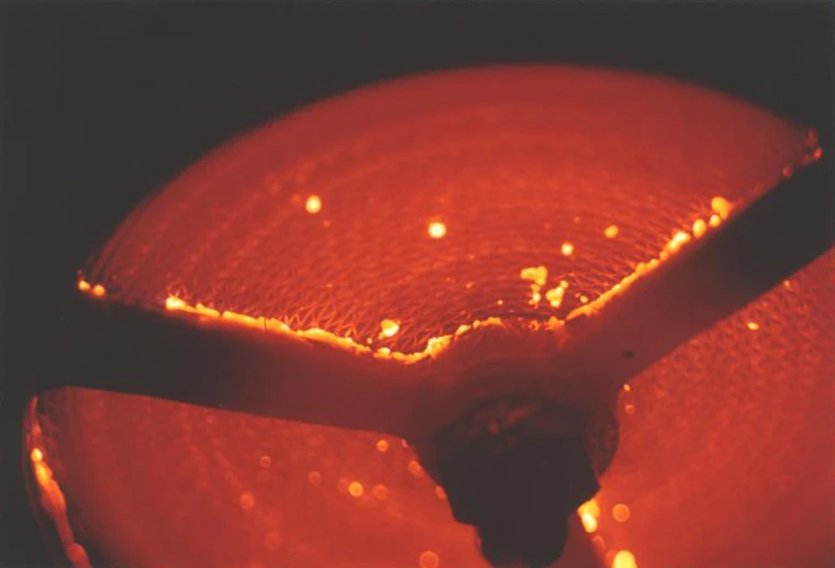
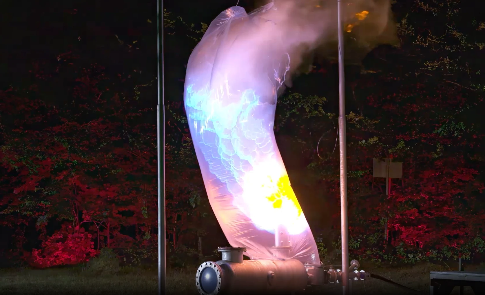
Provides Protection Against Atmospheric Deflagrations, Short-Time Burning
Easy Maintenance
Without Disassembling of the FLAMEFILTER®
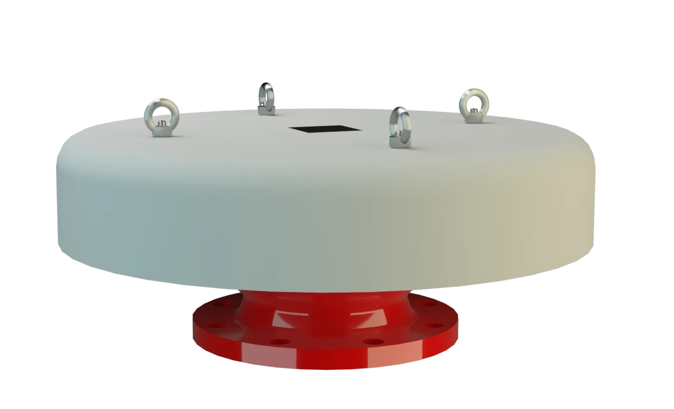
Function and Description
Proteção contra deflagrações atmosféricas
A calota de respiro do tipo PROTEGO® LH/AD oferece proteção contra deflagrações atmosféricas. O corta-chamas é usado para a proteção de abertura de compensação de pressão de instalações e vasos sem pressão, caso se possa excluir uma combustão estabilizada sobre o conjunto abafador de chamas. O equipamento é a solução ideal para a proteção de tubos de despressurização. O dispositivo impede a entrada de uma deflagração atmosférica para o interior de um vaso ou de uma instalação.
Componente Principal – Conjunto Abafador de Chamas PROTEGO®
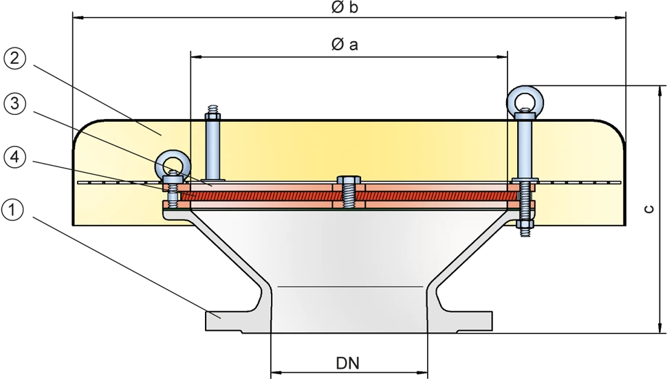
Os equipamentos do tipo PROTEGO® LH/AD são essencialmente compostos de um corpo (1), da tampa (2) e do conjunto abafador de chamas PROTEGO® (3). O dispositivo é fechado com uma tampa metálica de proteção sólida contra intempéries. Uma tela de proteção entre a tampa e corpo impede a entrada de corpos estranhos e de animais. A altura e o espaçamento dos FLAMEFILTER® (4) são adaptados dependendo das condições de uso. Indicando os parâmetros operacionais, como a temperatura e o grupo de explosão ou a composição da substância, se pode selecionar o ideal corta-chamas à prova de deflagração de final de linha.
Para os grupos de explosão IIA e IIC
Dependendo do tipo, os corta-chamas da série PROTEGO® LH/AD estão disponíveis para substâncias dos grupos de explosão IIA até IIC.
A versão padrão pode ser usada até uma temperatura de trabalho de +60°C. Divergindo disso, está disponível um número considerável de equipamentos com homologações especiais para temperaturas mais elevadas sob solicitação.
Teste de protótipo segundo a diretriz ATEX e EN ISO 16852, assim como outras Normas internacionais.
Product Data
Tabela de dimensões
Para selecionar o diâmetro nominal (DN), veja os diagramas de vazão nas páginas seguintes
| DN | a | b | c* | c* |
| IIB3 | IIC | |||
| 50 / 2" | 100 | 200 | 175 | 185 |
| 80 / 3" | 150 | 240 | 180 | 195 |
| 100 / 4" | 200 | 295 | 220 | 235 |
| 150 / 6" | 300 | 550 | 260 | 270 |
| 200 / 8" | 300 | 550 | 260 | 270 |
| 250 / 10" | 400 | 600 | 355 | 365 |
| 300 / 12" | 400 | 600 | 340 | 350 |
| 350 / 14" | 600 | 800 | 390 | 400 |
| 400 / 16" | 600 | 800 | 380 | 390 |
| 500 / 20" | 700 | 1000 | 400 | 410 |
| 600 / 24" | 800 | 1200 | 475 | 485 |
| 700 / 28" | 1000 | 1400 | 505 | 515 |
| 800 / 32" | 1200 | 1600 | 550 | 560 |
Dimensões em mm
* c são valores de referência. As medidas exatas dependem da conexão flangeada.
Seleção do grupo de explosão
| MESG | Gr. expl. (IEC / CEN) | Grupo gás (NEC) |
| ≥ 0,65 mm | IIB3 | C |
| < 0,5 mm | IIC | B |
Aprovações especiais sob solicitação
Indicação da temperatura máx. de trabalho
| ≤ 60°C / 140°F | Ttemperatura máxima de trabalho admissível em °C |
| - | Designation |
temperaturas de trabalho mais elevadas, sob solicitação
Seleção do material do corpo
| Execução | A | B |
| Corpo | Aço | Aço inoxidável |
| Tampa | Aço inoxidável | Aço inoxidável |
| Tela de proteção | Aço inoxidável | Aço inoxidável |
| Conjunto abafador de chamas | A, B | B |
Materiais especiais sob solicitação
Combinações de material do conjunto abafador de chamas
| Execução | A | B |
| Armação do FLAMEFILTER® | Aço | Aço inoxidável |
| FLAMEFILTER® | Aço inoxidável | Aço inoxidável |
Materiais especiais sob solicitação
Tipo de conexão flangeada
| EN 1092-1; Form B1 |
| ASME B16.5 CL 150 R.F. |
Outras conexões sob solicitação
Diagrama de vazão
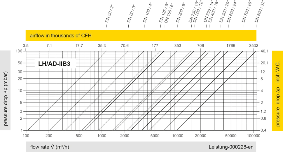
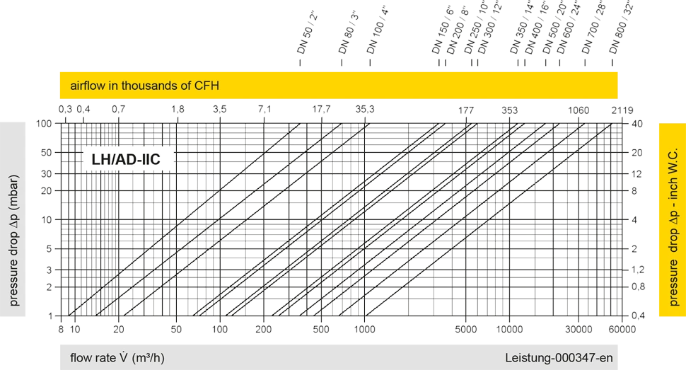
Este diagrama de vazão foi determinado em uma bancada de medição de vazão calibrada e certificada pela TÜV. A vazão V em m³/h se refere ao estado técnico padrão de ar, conforme ISO 6358 (20°C, 1bar). Para conversão em outras densidades e temperaturas, veja o cap. 1: Bases técnicas.


Se você tiver alguma dúvida, comentário ou sugestão, nossa equipe de especialistas terá prazer em ajudá-lo.
