Features
Cost Effective Device
Cost Effective Device
Vent Cap Provides Protection
Against Environmental Impact (Harsh Weather Conditions, Bird Nests, etc.)
Almost Maintenance Free
Almost Maintenance Free
Certified Flow Performance Curves
Certified Flow Performance Curves
Function and Description
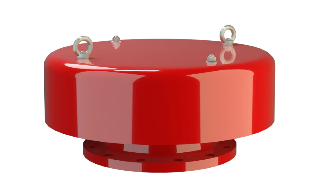
Capuz de proteção contra intempéries para ventilação eficiente
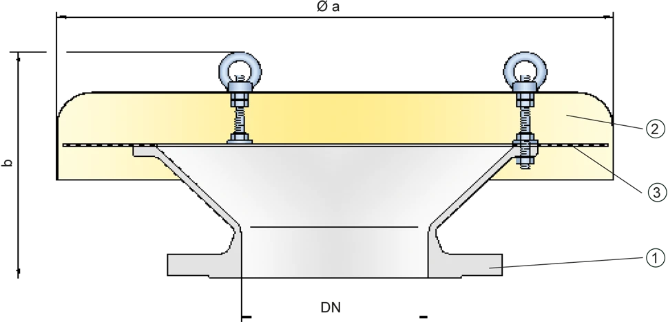
O dispositivo do tipo PROTEGO® EH/0S serve para o alívio de pressão e vácuo de vasos e aparelhos sem conservação da pressão. O equipamento evita a entrada de águas pluviais e sujeira nas aberturas de alívio de pressão e vácuo. A tampa de proteção não é à prova de propagação de chamas. Se corta-chamas à prova de detonação forem usados no tubo de alívio de pressão e vácuo para evitar um propagação de chamas e uma combustão estabilizada, os dispositivos do tipo PROTEGO® EH/0S podem ser usados como tampa de proteção. A calota de proteção contra intempéries PROTEGO® EH/0S é essencialmente composta de um corpo (1), da tampa (2) e de uma tela de proteção (3). O dispositivo é fechado com uma tampa sólida, em metal. A tela impede a entrada de corpos estranhos e protege contra animais nidificantes.
Product Data
Tabela de dimensões
Para escolher o diâmetro nominal (DN), veja o diagrama de vazão da página seguinte
| DN | 100 / 4" | 150 / 6" | 200 / 8" | 250 / 10" | 300 / 12" | 350 / 14" | 400 / 16" | 500 / 20" | 600 / 24" |
| a | 295 | 550 | 550 | 600 | 600 | 600 | 650 | 800 | 1000 |
| b | 230 | 240 | 240 | 325 | 320 | 335 | 370 | 385 | 520 |
Dimensões em mm
Seleção do material
| Execução | A | B |
| Corpo | Aço | Aço inoxidável |
| Tampa | Aço inoxidável | Aço inoxidável |
Materiais especiais sob solicitação
Tipo de conexão flangeada
| EN 1092-1; Form B1 |
| ASME B16.5 CL 150 R.F. |
Outras conexões sob solicitação
Diagrama de vazão
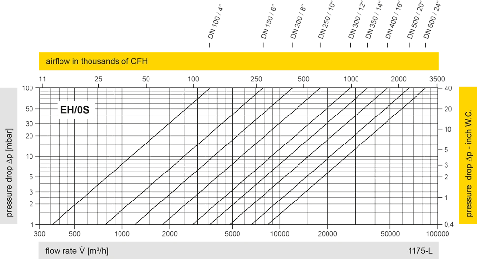
Este diagrama de vazão foi determinado em uma bancada de medição de vazão calibrada e certificada pela TÜV. A vazão V em m³/h se refere ao estado técnico padrão de ar, conforme ISO 6358 (20°C, 1bar). Para conversão em outras densidades e temperaturas, veja o cap. 1: Bases técnicas.


Se você tiver alguma dúvida, comentário ou sugestão, nossa equipe de especialistas terá prazer em ajudá-lo.
