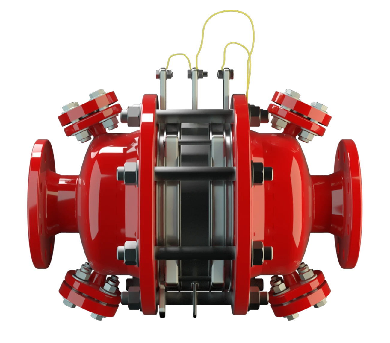
DA-SB-PTFE
In-Line Detonation Flame Arrester for stable detonations and deflagrations in a straight through design with shock absorber, bidirectional
Features
Low Costs
Temperature Sensors Possible
Bi-Directional Flame Transmission
Modular Design
Differnt Series
Aggressive, Sticky, or Polymerizing Products
Use of Patented Shock Wave Guide Tube Effect (SWGTE)
High-Tech Coating of the Housing

Main Component – PROTEGO® Flame Arrester Unit

For Explosion Group IIA
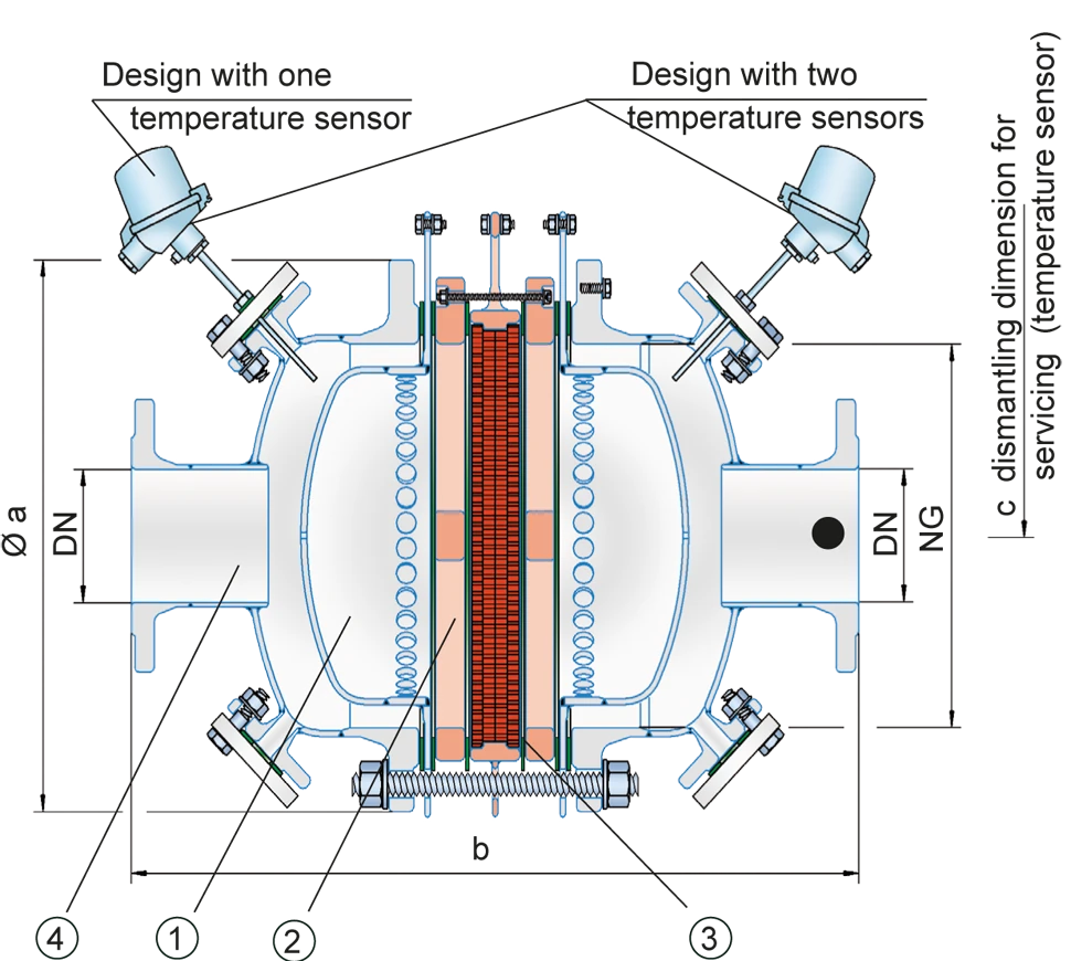
Tabela de dimensões
Para selecionar a combinação dos tamanhos nominais/diâmetros nominais (NG/DN), utilize os diagramas de vazão nas páginas seguintes
| NG | 150 / 6" | 150 / 6" | 200 / 8" | 300 / 12" |
| DN | 50 / 2" | 80 / 3" | 80 / 3" | 100 / 4" |
| a | 287 | 287 | 342 | 447 |
| b | 407 | 407 | 497 | 645 |
| c | 400 | 400 | 530 | 530 |
Dimensões em mm
Seleção do grupo de explosão
| MESG | Gr. expl. (IEC / CEN) | Grupo gás (NEC) |
| > 0,90 mm | IIA | D |
Aprovações especiais sob solicitação
Seleção da pressão máx. de trabalho
| NG | 150 / 6" | 150 / 6" | 200 / 8" | 300 / 12" |
| DN | 50 / 2" | 80 / 3" | 80 / 3" | 100 / 4" |
| Pmax | 2,4 | 1,1 | 1,2 | 1,2 |
Pmáx. = pressão de trabalho máxima admissível em bar absoluta, pressão de trabalho mais elevada sob solicitação
Indicação da temperatura máx. de trabalho
| ≤ 60°C / 140°F | Ttemperatura máxima de trabalho admissível em °C |
| - | Designation |
temperaturas de trabalho mais elevadas, sob solicitação
Material for housing
| Versão | A |
| Corpo | Aço |
| Absorvedor de choque | Aço |
| Vedação | PTFE |
| Conjunto abafador de chamas | A, B, C |
Materiais especiais sob solicitação
Combinações de material do conjunto abafador de chamas
| Design | A | B | C |
| FLAMEFILTER® cage | Steel with an ECTFE coating | Hastelloy | Stainless Steel |
| Spider rings | Steel with an ECTFE coating | Hastelloy | Stainless Steel |
| FLAMEFILTER®* | PTFE* | PTFE* | PTFE* |
| Spacer | PEEK / ETFE / FEP | PEEK / ETFE / FEP | PEEK / ETFE / FEP |
* electrically conductive
Special materials upon request
Tipo de conexão flangeada
| EN 1092-1; Form B1 |
| ASME B16.5 CL 150 R.F. |
Outras conexões sob solicitação
Diagrama de vazão
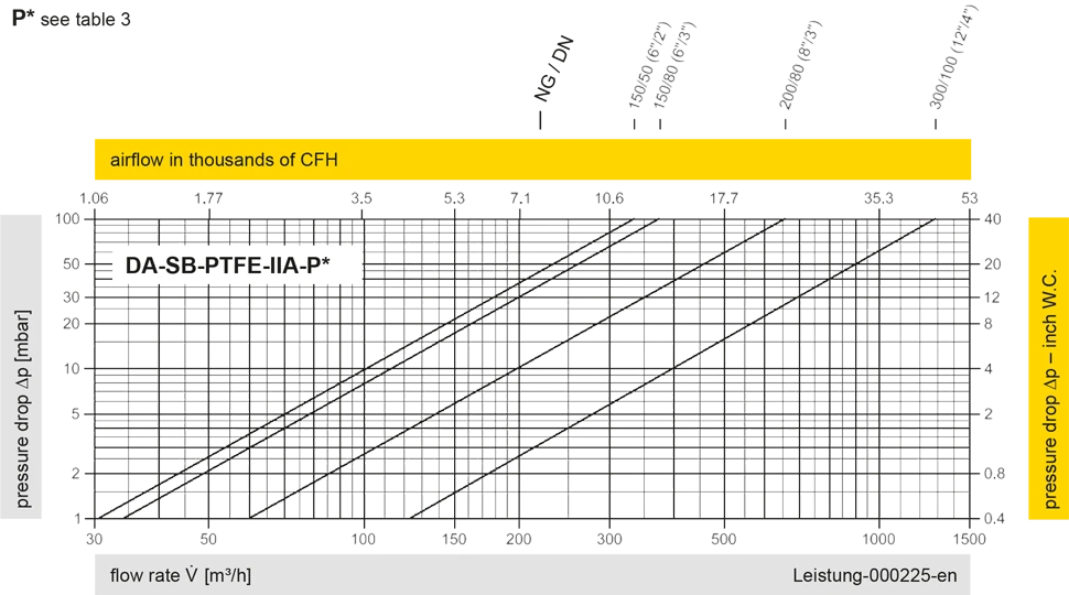
Este diagrama de vazão foi determinado em uma bancada de medição de vazão calibrada e certificada pela TÜV. A vazão V em m³/h se refere ao estado técnico padrão de ar, conforme ISO 6358 (20°C, 1bar). Para conversão em outras densidades e temperaturas, veja o cap. 1: Bases técnicas.


Se você tiver alguma dúvida, comentário ou sugestão, nossa equipe de especialistas terá prazer em ajudá-lo.
