Features
10% Technology
Extreme Tightness
Optimum Pressure Maintenance
High Flow Capacity
Separate Connections
Used in Explosion Hazardous Areas
Sturdy Housing Design
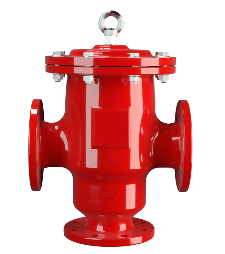
Válvula de alívio de pressão e vácuo com conexões separadas para respiração de pressão e de vácuo

Tecnologia de curso pleno
Tecnologia avançada de manufatura
Tabela de dimensões
Para selecionar o diâmetro nominal (DN), veja os diagramas de vazão nas páginas seguintes
| DN | 40 / 1½" | 50 / 2" | 65 / 2½" | 80 / 3" | 100 / 4" | 150 / 6" |
| a | 280 | 280 | 340 | 340 | 390 | 520 |
| b | 165 | 165 | 200 | 200 | 240 | 300 |
| c | 210 | 210 | 280 | 280 | 310 | 390 |
| d | 440 | 440 | 495 | 495 | 590 | 715 |
Dimensões em mm
DN maiores sob solicitação
Dimensões para a válvula de pressão e vácuo para tubulação com camisa de aquecimento sob solicitação
Seleção do material do corpo
| Execução | A | B |
| Corpo | Aço | Aço inoxidável |
| Camisa de aquecimento (DV / ZU-H-...) | Aço | Aço inoxidável |
| Sede de válvula | Aço inoxidável | Aço inoxidável |
| Vedação | PTFE | PTFE |
Os corpos também podem ser fornecidos com revestimento de ECTFE
Materiais especiais sob solicitação
Seleção do material do disco da válvula de pressão
| Execução | A | B | C | D |
| Faixa de pressão [mbar] | +2,0 até +3,5 | >+3,5 até +14 | >+14 até +60 | >+14 até +60 |
| Disco da válvula | Alumínio | Aço inoxidável | Aço inoxidável | Aço inoxidável |
| Vedação | FEP | FEP | metálica | PTFE |
Materiais especiais sob solicitação
Em caso de ajustes de pressão mais altos, usar o tipo DV/ZU-F
Seleção do material do disco da válvula de vácuo
| Execução | A | B | C | D | E | F |
| Faixa de pressão [mbar] | -3,5 até -5,0 | <-5,0 até -14 | <-14 até -35 | <-35 até -50 | <-14 até -35 | <-35 até -50 |
| Disco da válvula | Alumínio | Aço inoxidável | Aço inoxidável | Aço inoxidável | Aço inoxidável | Aço inoxidável |
| Vedação | FEP | FEP | metálica | metálica | PTFE | PTFE |
Materiais especiais, bem como ajustes de vácuo mais baixos sob solicitação
Tipo de conexão flangeada
| EN 1092-1; Form B1 |
| ASME B16.5 CL 150 R.F. |
Outras conexões sob solicitação
Diagrama de vazão
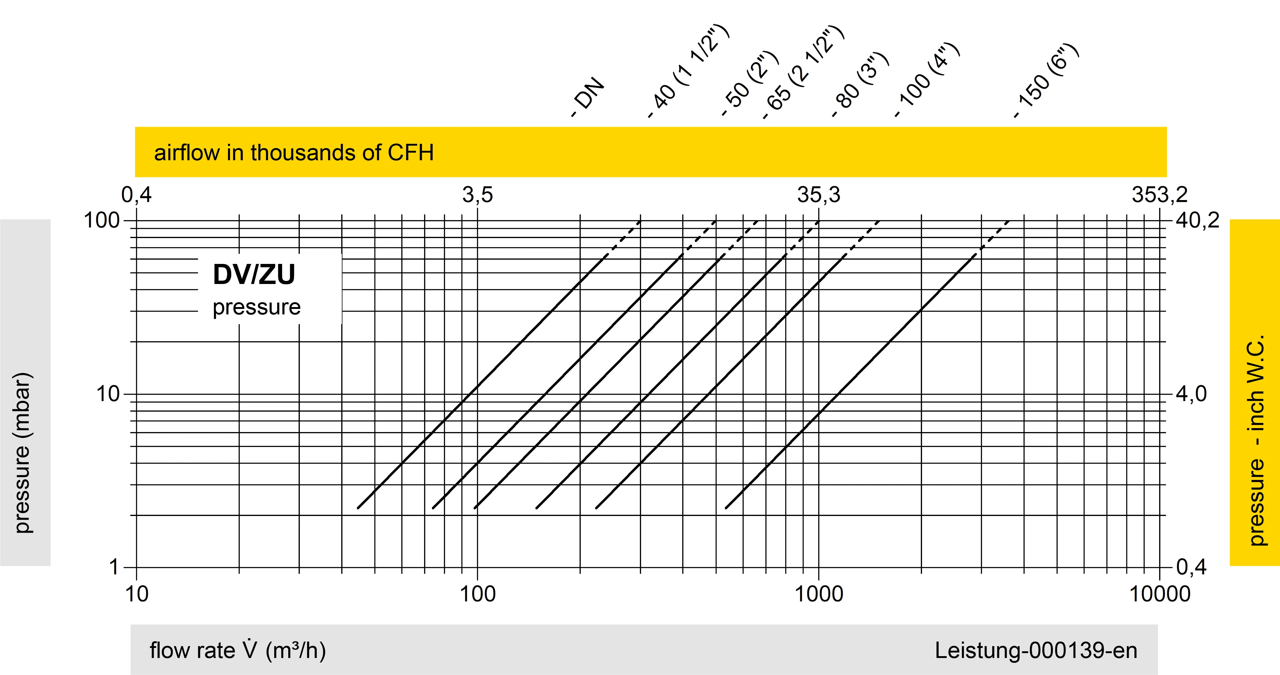
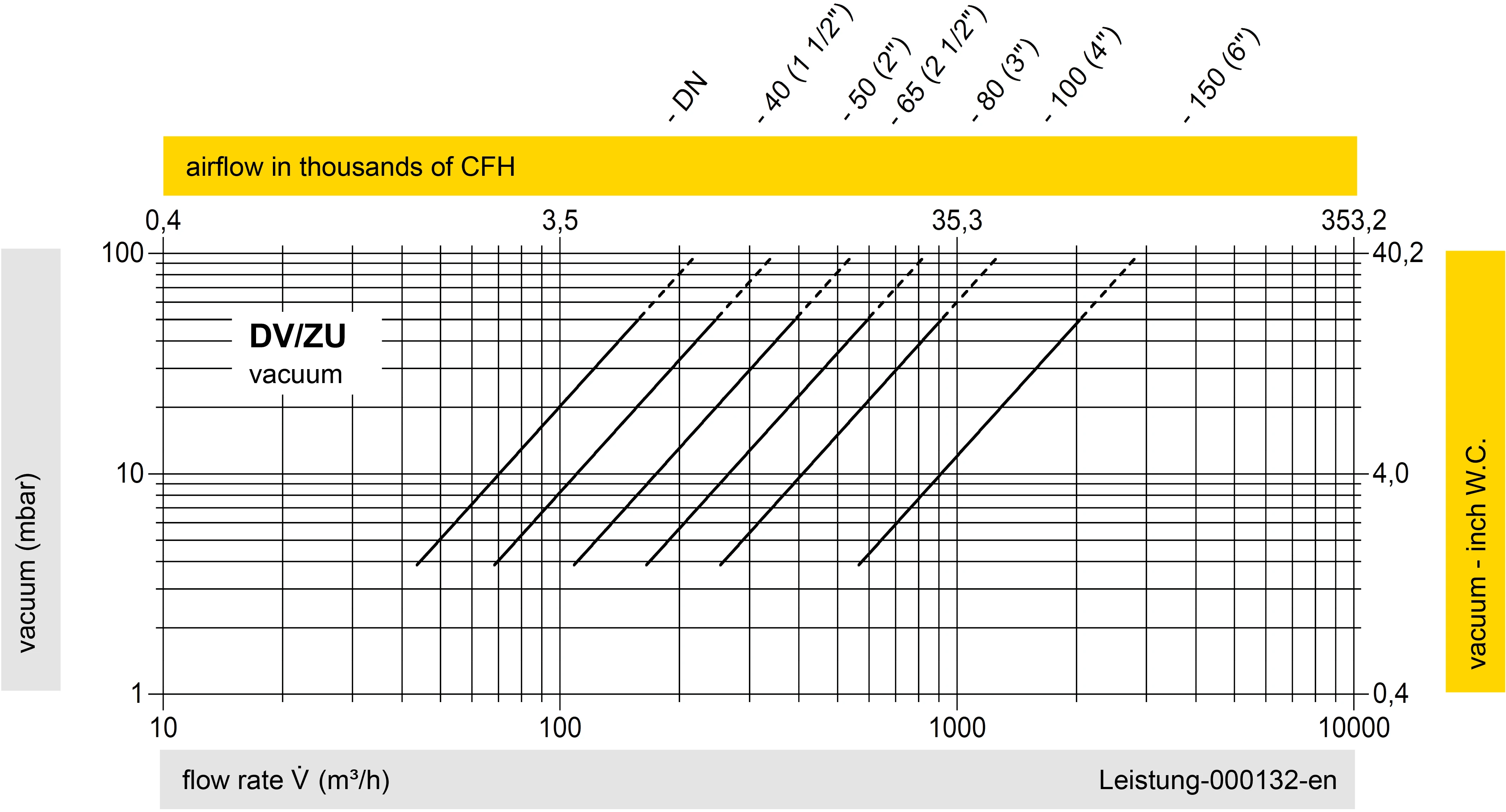
Este diagrama de vazão foi determinado em uma bancada de medição de vazão calibrada e certificada pela TÜV. A vazão V em m³/h se refere ao estado técnico padrão de ar, conforme ISO 6358 (20°C, 1bar). Para conversão em outras densidades e temperaturas, veja o cap. 1: Bases técnicas.
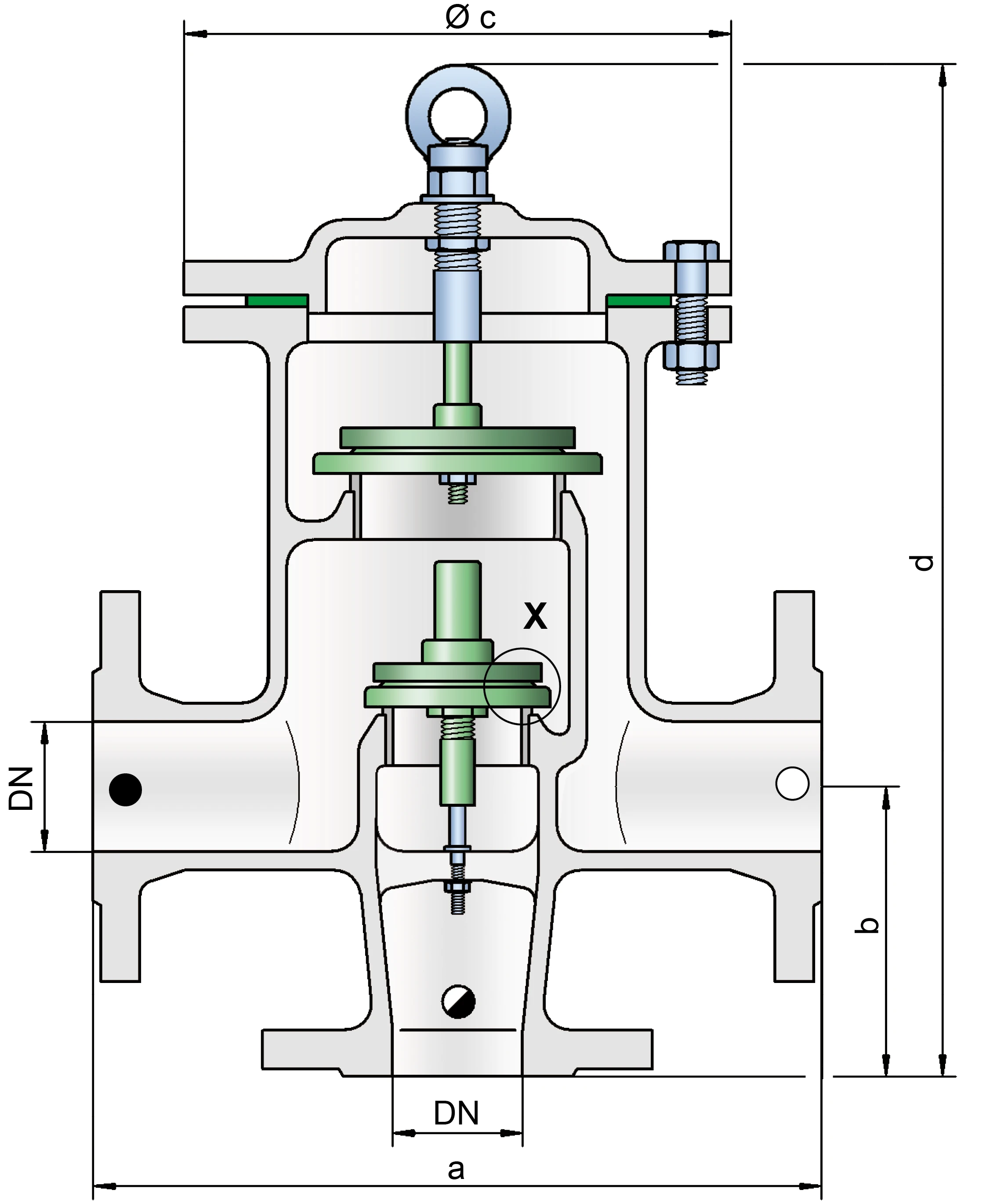
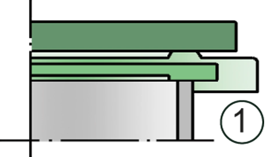
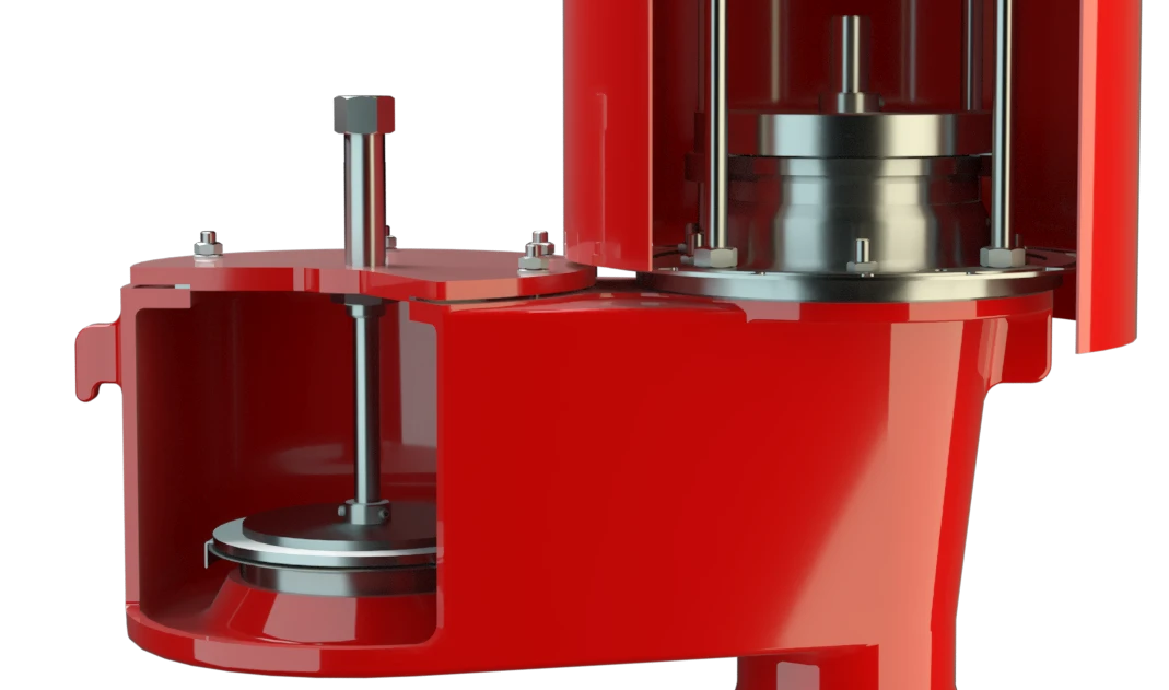
Detalhe X
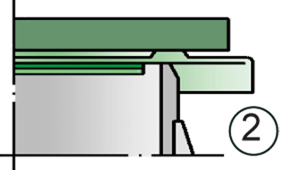
Detalhe X

conexão do tanque

alívio de vácuo

alívio de pressão


Se você tiver alguma dúvida, comentário ou sugestão, nossa equipe de especialistas terá prazer em ajudá-lo.
