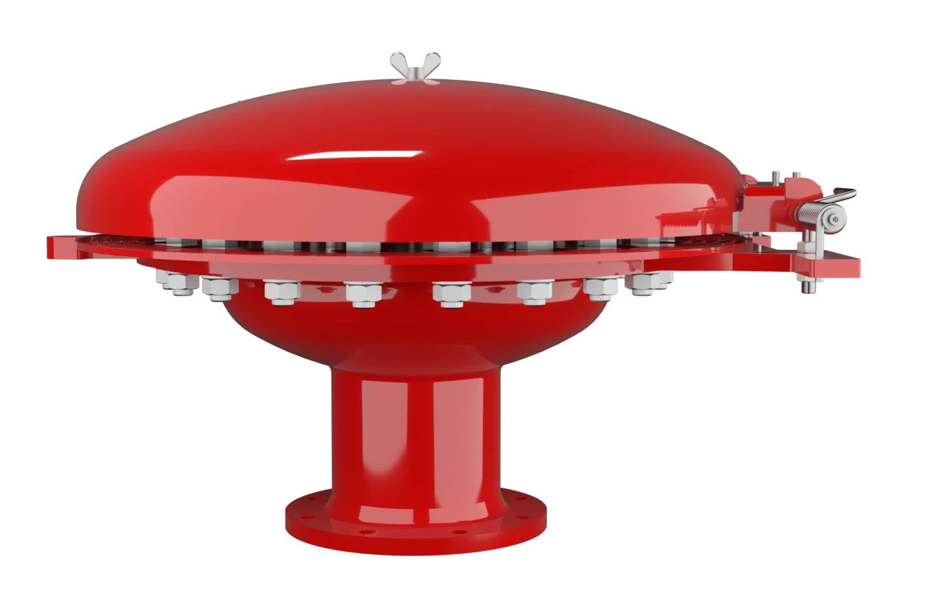
EB
Calota de respiro à prova de deflagração e combustão contínua
Features
Comprehensive Weather Protection
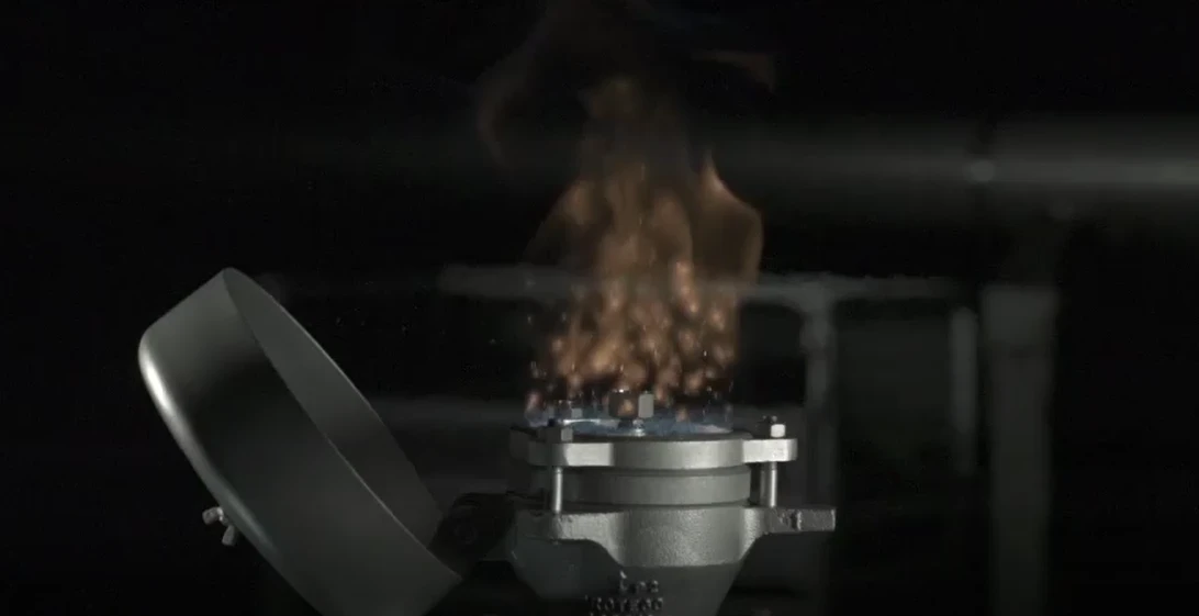
Visible Fire Indication by Tilting Weather Hood
Safety Against Deflagrations and Hydrocarbon Fires
Chemically Resistant
Modular Design
Easy Maintenance
Spare Parts
Proteção contra deflagração atmosférica e queima sustentada
Componente Principal – Conjunto Abafador de Chamas PROTEGO®

Para os grupos de explosão IIB a IIA
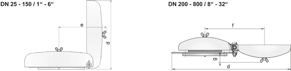
Tabela de dimensões DN 25 - 150 para EB-IIA e IIB
Para selecionar o diâmetro nominal (DN), veja o diagrama de vazão da página seguinte
| DN | 25 / 1" | 32 / 1¼“ | 40 / 1½“ | 50 / 2“ | 65 / 2½“ | 80 / 3“ | 100 / 4" | 125 / 5" | 150 / 6" |
| a | 218 / 8.58 | 218 / 8.58 | 218 / 8.58 | 218 / 8.58 | 218 / 8.58 | 353 / 13.90 | 353 / 13.90 | 353 / 13.90 | 353 / 13.90 |
| b | 113 / 4.45 | 113 / 4.45 | 113 / 4.45 | 113 / 4.45 | 113 / 4.45 | 113 / 4.45 | 113 / 4.45 | 113 / 4.45 | 113 / 4.45 |
| c | 232 / 9.13 | 232 / 9.13 | 232 / 9.13 | 232 / 9.13 | 232 / 9.13 | 306 / 12.05 | 306 / 12.05 | 306 / 12.05 | 306 / 12.05 |
| d | 222 / 8.74 | 222 / 8.74 | 222 / 8.74 | 222 / 8.74 | 222 / 8.74 | 355 / 13.98 | 355 / 13.98 | 355 / 13.98 | 355 / 13.98 |
| e | 217 / 8.54 | 217 / 8.54 | 217 / 8.54 | 217 / 8.54 | 217 / 8.54 | 322 / 12.68 | 322 / 12.68 | 322 / 12.68 | 322 / 12.68 |
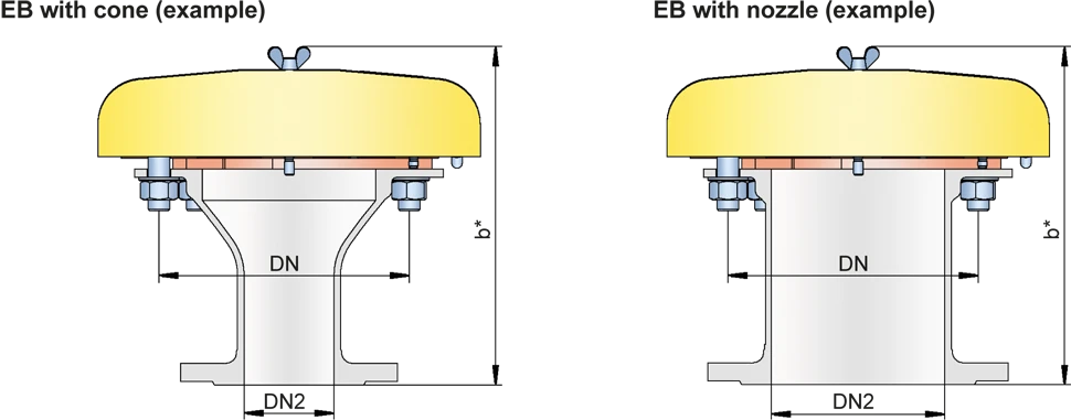
| EB-IIA and IIB with cone / nozzle** | |||||||||
| DN | 50 / 2" | 80 / 3" | 100 / 4" | 150 / 6" | |||||
| DN2 | ≤50 / 2“ | ≤80 / 3“ | ≤100 / 4 | ≤150 / 6“ | |||||
| b* | 238 / 9.37 | 263 / 10.35 | 383 / 15.08 | 313 / 12.32 | |||||
| Dimensions DN 200 - 800 / 8“ - 32“ for EB-IIA | |||||||||
| DN | 200 / 8" | 300 / 12" | 400 / 16" | 500 / 20" | 600 / 24" | 800 / 32“ | |||
| a | 405 / 15.94 | 555 / 21.85 | 705 / 27.75 | 855 / 33.66 | 1005 / 39.57 | 1210 / 47.64 | |||
| b | 177 / 6.97 | 206 / 8.11 | 235 / 9.25 | 265 / 10.43 | 294 / 11.57 | 330 / 12.99 | |||
| c | 496 / 19.53 | 650 / 25.59 | 802 / 31.57 | 987 / 38.86 | 1137 / 44.76 | 1336 / 52.60 | |||
| d | 900 / 35.43 | 1200 / 47.24 | 1500 / 59.06 | 1820 / 71.65 | 2120 / 83.46 | 2525 / 99.41 | |||
| f | 450 / 17.72 | 600 / 23.62 | 750 / 29.53 | 920 / 36.22 | 1070 / 42.13 | 1270 / 50.00 | |||
| g | 51 / 2.01 | 80 / 3.15 | 109 / 4.29 | 138 / 5.43 | 167 / 6.57 | 204 / 8.03 | |||
| EB-IIA with cone / nozzle** | |||||||||
| DN | 200 / 8" | 300 / 12" | 400 / 16" | 500 / 20" | 600 / 24" | 800 / 32" | |||
| DN2 | ≤200 / 8“ | ≤300 / 12“ | ≤400 / 16“ | ≤500 / 20“ | ≤600 / 24“ | ≤800 / 32“ | |||
| b* | 401 / 15.94 | 456 / 17.95 | 535 / 21.06 | 614 / 24.17 | 693 / 27.28 | 830 / 32.68 |
Dimensões em mm
** combinations (DN/DN2) please use the table on the following page
Combination (DN/DN2) for EB with cone
Flow capacity charts for EB-DN/DN2-IIA/IIB with cone upon request
| DN | 50 / 2“ | 80 / 3“ | 100 / 4“ | 150 / 6“ | 200 / 8“ | 300 / 12“ | 400 / 16“ | 500 / 20“ | 600 / 24“ | 800 / 32“ |
| DN2 | ||||||||||
| 20 / ¾“ | IIA / IIB | IIA / IIB | IIA / IIB | IIA / IIB | ||||||
| 25 / 1“ | IIA / IIB | IIA / IIB | IIA / IIB | IIA / IIB | ||||||
| 32 / 1¼" | IIA / IIB | IIA / IIB | IIA / IIB | IIA / IIB | ||||||
| 40 / 1½" | IIA / IIB | IIA / IIB | IIA / IIB | IIA / IIB | ||||||
| 50 / 2“ | IIA / IIB | IIA / IIB | IIA / IIB | IIA / IIB | IIA | |||||
| 65 / 2½“ | IIA / IIB | IIA / IIB | IIA / IIB | |||||||
| 80 / 3“ | IIA / IIB | IIA / IIB | IIA / IIB | IIA | IIA | |||||
| 100 / 4“ | IIA / IIB | IIA / IIB | IIA | IIA | ||||||
| 125 / 5“ | IIA / IIB | IIA | ||||||||
| 150 / 6“ | IIA / IIB | IIA | IIA | IIA | ||||||
| 200 / 8“ | IIA | IIA | IIA | IIA | IIA | |||||
| 250 / 10“ | IIA | IIA | IIA | |||||||
| 300 / 12“ | IIA | IIA | IIA | |||||||
| 350 / 14“ | IIA | IIA | ||||||||
| 400 / 16“ | IIA | IIA | IIA | |||||||
| 450 / 18“ | IIA | IIA | IIA | |||||||
| 500 / 20“ | IIA | IIA | ||||||||
| 600 / 24“ | IIA | |||||||||
| 700 / 28“ | IIA |
Seleção do grupo de explosão
| MESG | Gr. expl. (IEC / CEN) | Grupo gás (NEC) |
| > 0,90 mm | IIA | D |
| ≥ 0,50 mm | IIB | B |
Aprovações especiais sob solicitação
Seleção do material do corpo
| Execução | A | B |
| flange ring | Aço | Aço inoxidável |
| Tampa | Aço | Aço inoxidável |
| cone / nozzle | Aço | Aço inoxidável |
| Conjunto abafador de chamas | A, B, C | B, C |
Materiais especiais sob solicitação
Combinações de material do conjunto abafador de chamas
| Execução | A | B | C |
| Armação do jogo de FLAMEFILTER® | Aço | Aço inoxidável | Aço inoxidável / Hastelloy |
| FLAMEFILTER® | Aço inoxidável | Aço inoxidável | Hatselloy |
| Anel aletado | Aço | Aço inoxidável | Aço inoxidável / Hastelloy |
Materiais especiais sob solicitação
Tipo de conexão flangeada
| EN 1092-1 ou DIN 2501; PN10 / 16 |
| ASME B16.5 CL 150 R.F. |
Outras conexões sob solicitação
Diagrama de vazão
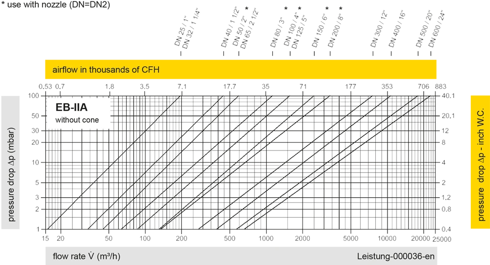
Este diagrama de vazão foi determinado em uma bancada de medição de vazão calibrada e certificada pela TÜV. A vazão V em m³/h se refere ao estado técnico padrão de ar, conforme ISO 6358 (20°C, 1bar). Para conversão em outras densidades e temperaturas, veja o cap. 1: Bases técnicas.
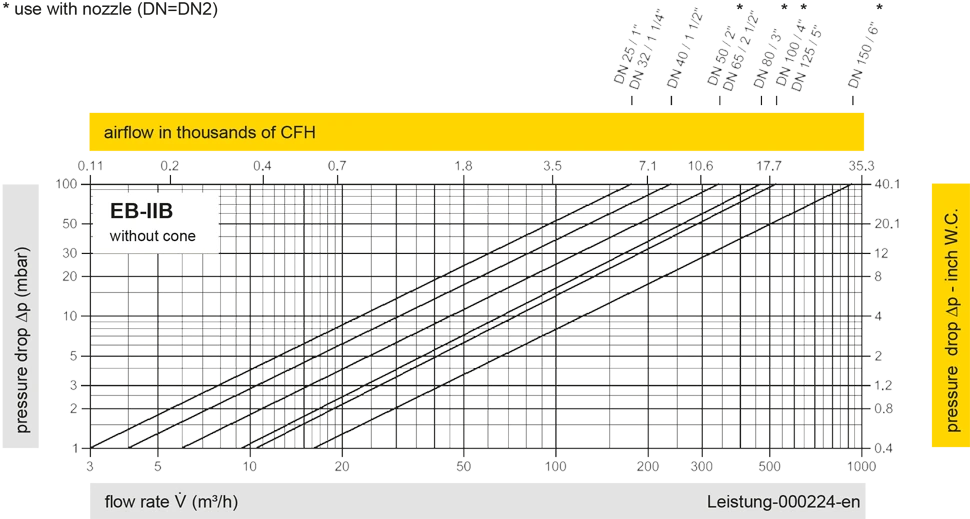
Este diagrama de vazão foi determinado em uma bancada de medição de vazão calibrada e certificada pela TÜV. A vazão V em m³/h se refere ao estado técnico padrão de ar, conforme ISO 6358 (20°C, 1bar). Para conversão em outras densidades e temperaturas, veja o cap. 1: Bases técnicas.


Se você tiver alguma dúvida, comentário ou sugestão, nossa equipe de especialistas terá prazer em ajudá-lo.
