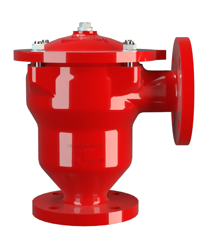
DR/ES-V
In-Line Detonation Flame Arrester with integrated pressure relief valve, for stable detonations and deflagrations in right angle design with shock absorber, unidirectional
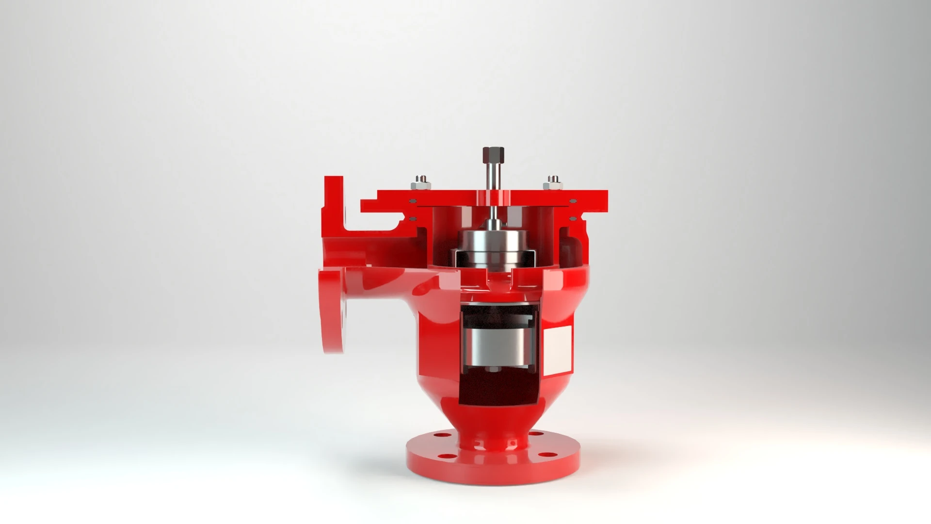
Features
Combinación en un único dispositivo
Uso óptimo como válvula de rebose
Número reducido de discos FLAMEFILTER®
Montaje y desmontaje más rápido
Seguridad frente a explosiones
Válvula de retención
Amplio rango de aplicaciones
Piezas de recambio
Protects Against Deflagration and Stable Detonation
In-Line Detonation Flame Arrester for Vent Headers

For Explosion Groups IIA to IIB3
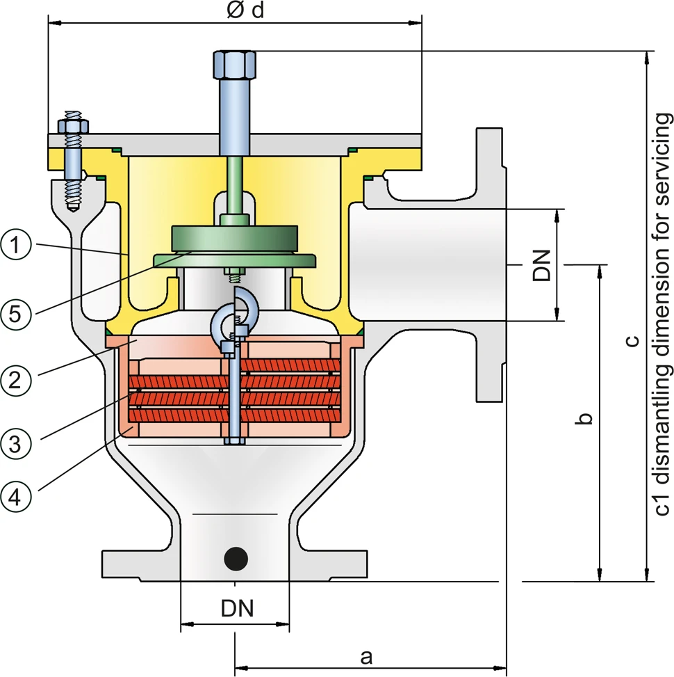
Dimensiones
To select the nominal size Nominal size The nominal size is an alphanumeric designation of size for components in a piping system, used for reference purposes, comprising the letters DN followed by a dimensionless integer that is indirectly related to the physical size of the bore or outside diameter of the connections, expessed in millimeters. (DN), please use the flow capacity charts on the following pages
| DN | 25 / 1" | 32 / 1¼“ | 40 / 1½“ | 50 / 2“ | 65 / 2½“ | 80 / 3“ | 100 / 4“ | 125 / 5“ | 150 / 6" | 200 / 8" |
| a | 125 / 4.92 | 125 / 4.92 | 153 / 6.02 | 155 / 6.10 | 198 / 7.80 | 200 / 7.87 | 250 / 9.84 | 332 / 13.07 | 335 / 13.19 | 425 / 16.73 |
| b | 140 / 5.51 | 140 / 5.51 | 183 / 7.20 | 185 / 7.28 | 223 / 8.78 | 225 / 8.86 | 290 / 11.42 | 357 / 14.06 | 360 / 14.17 | 505 / 19.88 |
| c | 237 / 9.33 | 237 / 9.33 | 305 / 12.01 | 305 / 12.01 | 395 / 15.55 | 395 / 15.55 | 460 / 18.11 | 575 / 22.64 | 575 / 22.64 | 863 / 33.98 |
| c1 | 345 / 13.58 | 345 / 13.58 | 410 / 16.14 | 410 / 16.14 | 530 / 20.87 | 530 / 20.87 | 615 / 24.21 | 790 / 31.10 | 790 / 31.10 | 1295 / 50.98 |
| d | 149 / 5.87 | 149 / 5.87 | 210 / 8.27 | 210 / 8.27 | 275 / 10.83 | 275 / 10.83 | 325 / 12.80 | 460 / 18.11 | 460 / 18.11 | 620 / 24.41 |
Dimensiones en mm / pulgadas
Selección del grupo de explosión
| MESG | Expl. Gr. (IEC / CEN) | Gas Group (NEC) |
| > 0,90 mm | IIA | D |
| ≥ 0,65 mm | IIB3 | C |
Special approvals upon request
Selección de la máxima presión de operación
| Expl. Gr. | DN | 25 / 1" | 32 / 1¼" | 40 / 1½" | 50 / 2" | 65 / 2½" | 80 / 3" | 100 / 4" | 125 / 5" | 150 / 6" | 200 / 8" |
| IIA | Pmax | 4,0 / 58.0 | 4,0 / 58.0 | 4,0 / 58.0 | 4,0 / 58.0 | 2,9 / 42.1 | 2,9 / 42.1 | 2,0 / 29.0 | 2,0 / 29.0 | 2,0 / 29.0 | 1,2 / 17.4 |
| IIB3 | Pmax | 3,0 / 43.5 | 3,0 / 43.5 | 2,0 / 29.0 | 2,0 / 29.0 | 2,0 / 29.0 | 2,0 / 29.0 | 1,5 / 21.7 | 1,4 / 20.3 | 1,4 / 20.3 | 1,1 / 15.9 |
Pmax = maximum allowable operating pressure in bar / psi absolute, higher operating pressure upon request
Especificación de la máx. temperatura de operación
| ≤ 60°C / 140°F | Tmaximum allowable operating temperature in °C |
| - | Designation |
higher operating temperatures upon request
Selección de materiales para la vivienda
| Design | B | C | D |
| Design | Steel | Stainless Steel | Hastelloy |
| Heating jacket (DR / ES-V-H-...) | Steel | Stainless Steel | Stainless Steel |
| Cover with shock absorber | Steel | Stainless Steel | Hastelloy |
| Gaskets | PTFE | PTFE | PTFE |
| Valve seat Valve seat The valve seat is a component on which the valve pallet rests when the valve is closed. | Stainless Steel | Stainless Steel | Stainless Steel |
| Flame arrester unit Flame arrester unit Flame arrester casing with FLAMEFILTER® set. | A | C, D | E |
The housing and the cover with shock absorber can also be delivered in steel with an ECTFE coating Coating Coating is the application of a firmly adhering layer of shapeless material to the surface of a workpiece. .
Special materials upon request
Combinación de materiales para la unidad apagallamas
| Design | A | C | D | E |
| FLAMEFILTER® cage | Steel | Stainless Steel | Stainless Steel | Hastelloy |
| FLAMEFILTER®* | Stainless Steel | Stainless Steel | Hastelloy | Hastelloy |
| Spacer Spacer The spacer is a component that is generally used in a PROTEGO® flame arrester as a spacer within the FLAMEFILTER® se | Stainless Steel | Stainless Steel | Hastelloy | Hastelloy |
* the FLAMEFILTER® are also available in the materials Tantalum, Inconel, Copper, etc. when the listed housing and cage materials are used.
Special materials upon request
Selection of valve pallet
| Design | A | B | C |
| Pressure range | I | II | III |
| Set pressure [mbar] | +2.0 up to +3.5 | >+3.5 up to +14 | >+14 up to 35 |
| [inch W.C.] | +0.8 up to +1.4 | >+1.4 up to +5.6 | >+5.6 up to 14 |
| Valve pallet | Aluminium | Stainless Steel | Stainless Steel |
| Sealing | FEP | FEP | Metal to Metal |
Tipo de bridas de conexión
| EN 1092-1; Form B1 |
| ASME B16.5 CL 150 R.F. |
other connections upon request
Diagrama de flujo volumétrico
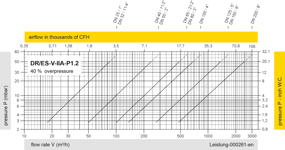
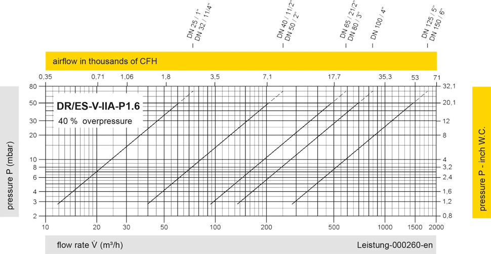
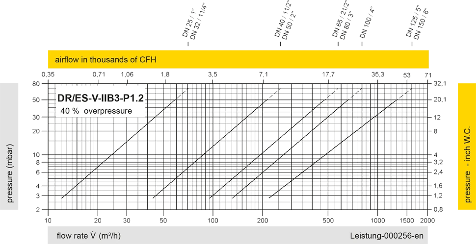
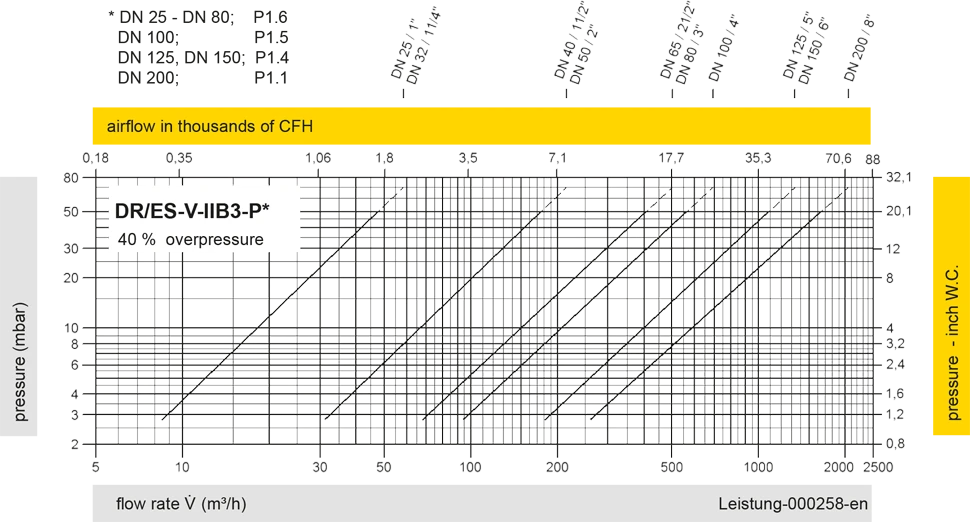
Los diagramas de flujo volumétrico han sido determinados con un banco de pruebas de caudal calibrado y certifi - cado por TÜV. El flujo volumétrico V. en [m³/h] y el CFH se refi eren a las condiciones estándar de referencia de aire según ISO 6358 (20°C, 1bar). La conversión a otras densidades y temperaturas están referidas en el Vol. 1: “Fundamentos Técnicos”.


Si tienes alguna pregunta, comentario o sugerencia, nuestro equipo de expertos estará encantado de ayudarte.
