Features
Protección integral contra la intemperie
La caperuza con pantalla de protección protege la unidad apagallamas PROTEGO® frente a impactos ambientales, como nidos de animales y condiciones meteorológicas adversas
Varios tamaños
Available for DN 50/2"– bis DN 800/32"– Pipes
Amplio rango de aplicaciones
for Elevated Operating Temperatures and Pressures
Piezas de recambio
Cost-Effective Spare Parts
Bajo coste
Low Operating and Lifecycle Costs
Seguridad
Proporciona protección contra deflagraciones atmosféricas y combustión de corta duración
Fácil mantenimiento
Without Disassembling of the FLAMEFILTER®
Function and Description
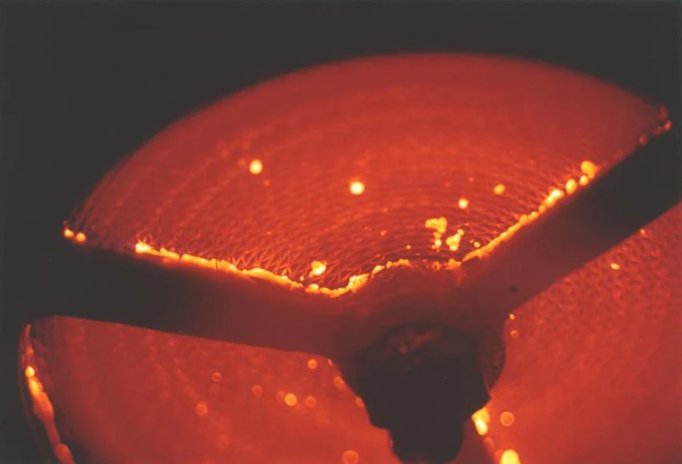
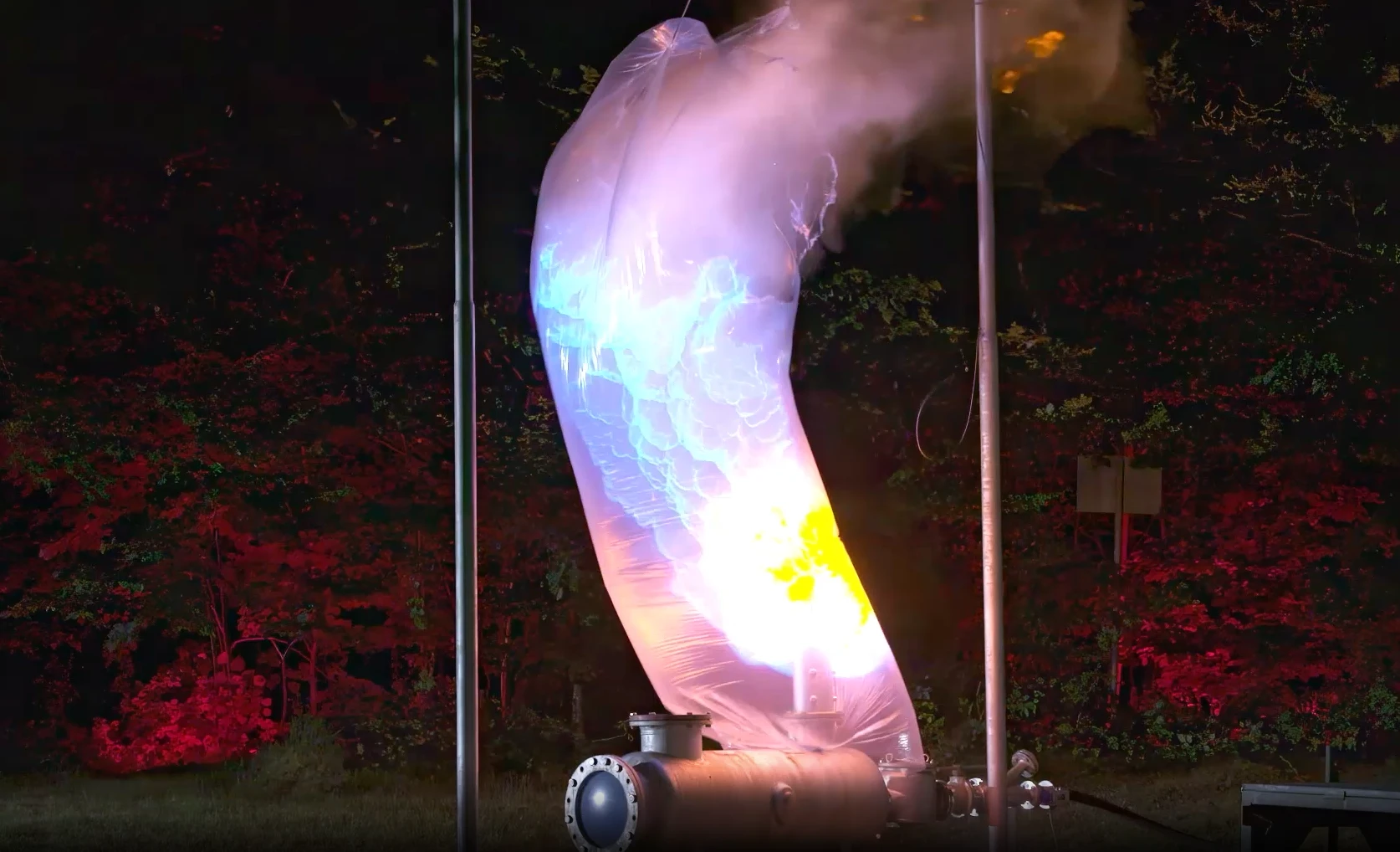
Protección contra deflagraciones atmosféricas
El
Pressure/vacuum relief valve
Pressure/vacuum relief valve is an umbrella term that includes pressure or vacuum relief valve as well as pressure and vacuum relief valve.
apagallamas final de línea a prueba de deflagraciones PROTEGO® LH/AD protege contra deflagraciones atmosféricas. El equipo se instala normalmente en las líneas de venteo de tanques o depósitos y plantas que no están presurizados. Para su segura aplicación es importante asegurarse de que no haya peligro de combustión prolongada, por eso habitualmente se instala en líneas que emiten vapor únicamente durante un corto periodo de tiempo. Este equipo evita la transmisión de la llama de la deflagración atmosférica al tanque o a la planta.
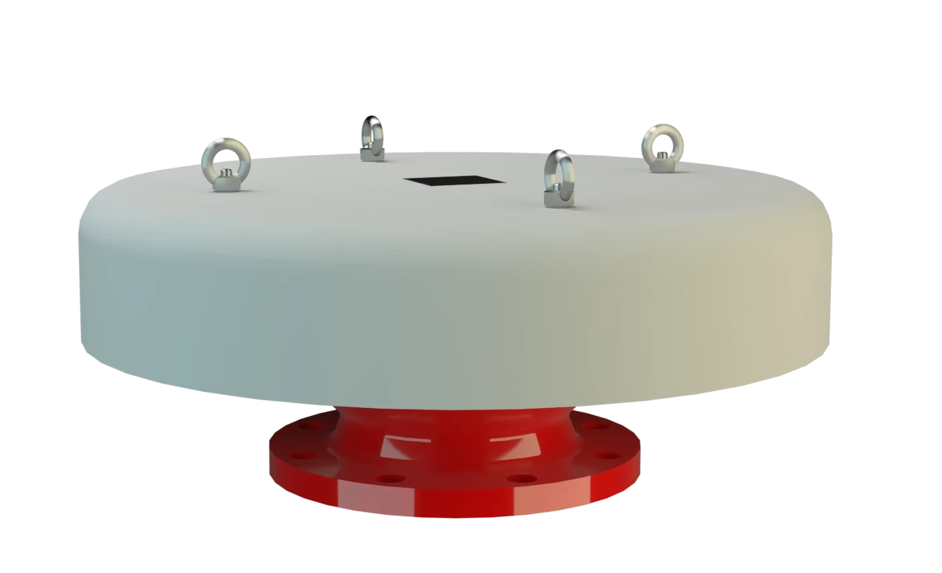
Componente Principal: Apagallamas PROTEGO®
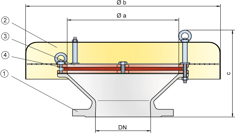
El equipo PROTEGO® LH/AD consta de un cuerpo (1), una capucha de protección (2) y la unidad apagallamas PROTEGO® (3) y está equipado con una capucha de protección de metal. La pantalla de protección está instalada entre la capucha de protección y el cuerpo para evitar que entren pájaros. El ancho de intersticio del filtro de llamas FLAMEFILTER® (4) dependerá del uso al que se destine el apagallamas. La información detallada de las condiciones de operación como la temperatura, el grupo de explosión y la composición del fluido, permite a PROTEGO® seleccionar el mejor apagallamas final de línea a prueba de deflagraciones para su aplicación.
Para los grupos de explosión IIA a IIC
La serie PROTEGO® LH/AD final de línea a prueba de deflagraciones se encuentra disponible para los grupos de explosión desde IIA a IIC (grupos NEC de D a B).
El diseño estándar puede utilizarse con temperaturas de operación de hasta +60°C / 140°F. Bajo demanda también pueden fabricarse equipos con homologación especial para temperaturas más altas.
Modelo homologado según la Directiva válida actualmente y EN ISO 16852 así como según otros estándares internacionales.
Product Data
Dimensiones
Para seleccionar el tamaño nominal (DN), utilícense los diagramas de caudal en la páginas siguientes
| DN | a | b | c* | c* |
| IIB3 | IIC | |||
| 50 / 2" | 100 / 3.94 | 200 / 7.87 | 175 / 6.89 | 185 / 7.28 |
| 80 / 3" | 150 / 5.91 | 240 / 9.45 | 180 / 7.09 | 195 / 7.68 |
| 100 / 4" | 200 / 7.87 | 295 / 11.61 | 220 / 8.66 | 235 / 9.25 |
| 150 / 6" | 300 / 11.81 | 550 / 21.65 | 260 / 10.24 | 270 / 10.63 |
| 200 / 8" | 300 / 11.81 | 550 / 21.65 | 260 / 10.24 | 270 / 10.63 |
| 250 / 10" | 400 / 15.75 | 600 / 23.62 | 355 / 13.98 | 365 / 14.37 |
| 300 / 12" | 400 / 15.75 | 600 / 23.62 | 340 / 13.39 | 350 / 13.78 |
| 350 / 14" | 600 / 23.62 | 800 / 31.50 | 390 / 15.35 | 400 / 15.75 |
| 400 / 16" | 600 / 23.62 | 800 / 31.50 | 380 / 14.96 | 390 / 15.35 |
| 500 / 20" | 700 / 27.56 | 1000 / 39.37 | 400 / 15.75 | 410 / 16.14 |
| 600 / 24" | 800 / 31.50 | 1200 / 47.24 | 475 / 18.70 | 485 / 19.09 |
| 700 / 28" | 1000 / 39.37 | 1400 / 55.12 | 505 / 19.88 | 515 / 20.28 |
| 800 / 32" | 1200 / 47.24 | 1600 / 62.99 | 550 / 21.65 | 560 / 22.05 |
Dimensiones en mm / pulgadas
* medida c para la conexión DIN PN 10
Selección del grupo de explosión
| MESG (IEMS) | Expl. Gr. (IEC / CEN) | Gas Group (NEC) |
| ≥ 0,65 mm | IIB3 | C |
| < 0,5 mm | IIC | B |
Homologaciones especiales bajo demanda
Especificación de la máx. temperatura de operación
| ≤ 60°C / 140°F | Tmáx - Temperatura máxima de operación admisible en °C |
| - | Designation |
Temperaturas de operación más altas bajo demanda
Selección de materiales para la vivienda
| Diseño | A | B |
| Cuerpo | Acero | Acero inoxidable |
| Capucha de protección | Acero inoxidable | Acero inoxidable |
| Pantalla de protección | Acero inoxidable | Acero inoxidable |
| Unidad apagallamas | A, B | B |
Materiales especiales bajo petición
Combinación de materiales para la unidad apagallamas
| Diseño | A | B |
| FLAMMENFILTER® Jaula | Acero | Acero inoxidable |
| FLAMMENFILTER® | Acero inoxidable | Acero inoxidable |
Materiales especiales bajo petición
Tipo de bridas de conexión
| EN 1092-1; Form B1 |
| ASME B16.5 CL 150 R.F. |
Otros tipos bajo petición
Diagrama de flujo volumétrico
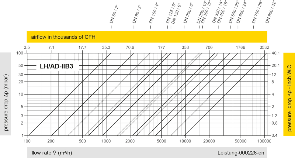
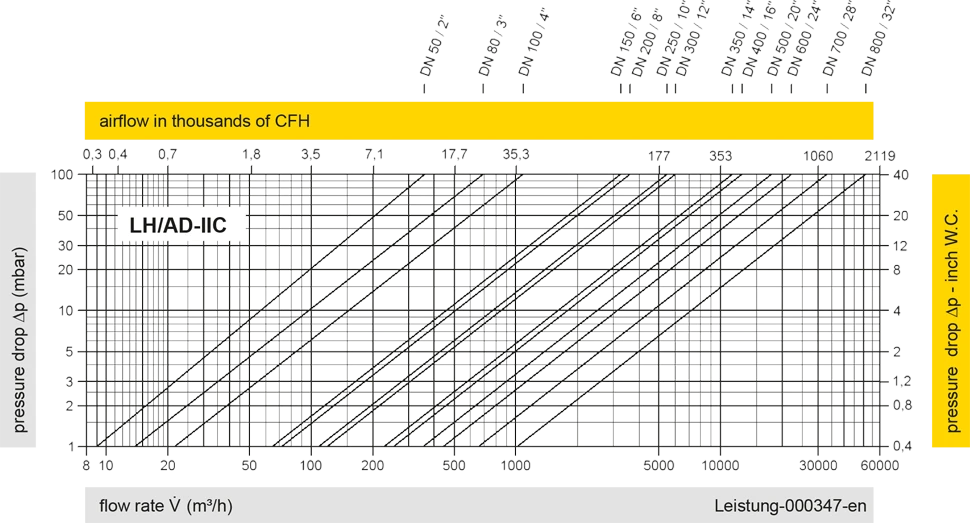
Los diagramas de flujo volumétrico han sido determinados con un banco de pruebas de caudal calibrado y certifi - cado por TÜV. El flujo volumétrico V. en [m³/h] y el CFH se refi eren a las condiciones estándar de referencia de aire según ISO 6358 (20°C, 1bar). La conversión a otras densidades y temperaturas están referidas en el Vol. 1: “Fundamentos Técnicos”.


Si tienes alguna pregunta, comentario o sugerencia, nuestro equipo de expertos estará encantado de ayudarte.
