EF/V-IIB3
Detonation Flame Arrester, Detonation-proof foot valve for suction lines
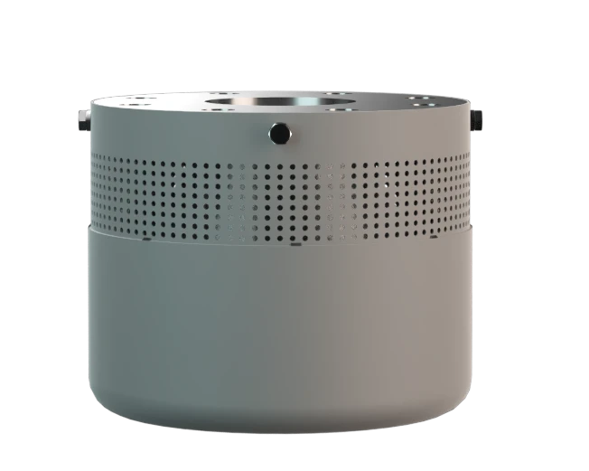
Features
Válvula de retención
Cumple los requisitos de la Norma TRGS
Filtro de aspiración especial
Seguridad frente a explosiones
Prácticamente libre de mantenimiento
Para líquidos inflamables
Protege la línea de succión en un tanque de almacenamiento

Válvula de pie a prueba de detonación: evita la transmisión de llama y la destrucción

Para el grupo de explosión IIB3
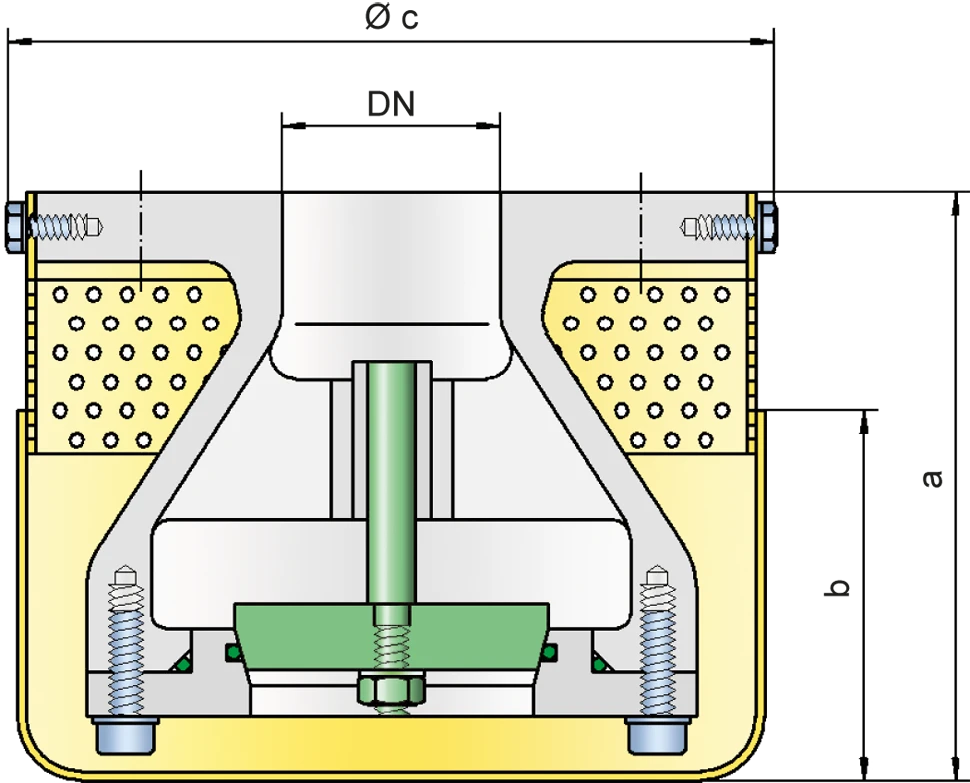
Dimensiones
To select the nominal size Nominal size The nominal size is an alphanumeric designation of size for components in a piping system, used for reference purposes, comprising the letters DN followed by a dimensionless integer that is indirectly related to the physical size of the bore or outside diameter of the connections, expessed in millimeters. (DN), please use the flow capacity chart on the following pages
| DN | 25 / 1" | 32 / 1¼“ | 40 / 1½“ | 50 / 2" | 65 / 2½“ | 80 / 3" | 100 / 4" | 125 / 5" | 150 / 6" | 200 / 8" | 250 / 10" |
| a | 125 / 4.92 | 125 / 4.92 | 135 / 5.31 | 135 / 5.31 | 160 / 6.29 | 160 / 6.29 | 200 / 7.87 | 235 / 9.25 | 260 / 10.24 | 400 / 15.75 | 450 / 17.72 |
| b | 85 / 3.35 | 85 / 3.35 | 85 / 3.35 | 85 / 3.35 | 95 / 3.74 | 95 / 3.74 | 125 / 4.92 | 130 / 5.12 | 135 / 5.31 | 175 / 6.89 | 200 / 7.87 |
| c | 155 / 6.10 | 155 / 6.10 | 180 / 7.09 | 180 / 7.09 | 210 / 8.27 | 210 / 8.27 | 250 / 9.84 | 310 / 12.20 | 365 / 14.37 | 480 / 18.90 | 565 / 22.24 |
Dimensiones en mm / pulgadas
Selección del grupo de explosión
| MESG | Expl. Gr. (IEC / CEN) | Gas Group (NEC) |
| > 0,90 mm | IIA | D |
| ≥ 0,65 mm | IIB3 | C |
Special approvals upon request
Especificación de la máx. temperatura de operación
| ≤ 60°C / 140°F | Tmaximum allowable operating temperature Operating temperature Temperature reached when the equipment is operating under design conditions. in °C |
| - | Designation |
higher operating temperatures upon request
Selección de materiales para la vivienda
| Design | A | B | C | D |
| Housing Housing A housing is a solid shell, which surrounds a content, either protecting the content from external influences, or protecting the environment from the content. | Steel | Stainless Steel | Steel | Stainless Steel |
| Valve | Stainless Steel | Stainless Steel | Stainless Steel | Stainless Steel |
| Gasket (Valve) | PTFE | PTFE | PTFE | PTFE |
| Gasket (Housing) | FPM | FPM | PTFE | PTFE |
| Strainer | Stainless Steel | Stainless Steel | Stainless Steel | Stainless Steel |
Special materials upon request
Tipo de bridas de conexión
| EN 1092-1; Form B1 |
| ASME B16.5 CL 150 F.F. |
other connections upon request
Diagrama de flujo volumétrico
The volume flow V in m³/h was determined with water according to DIN EN 60534 at a temperature Tn = 20°C and an atmospheric pressure pn = 1,013 bar, kinematic viscosity v = 10-6 m²/s
To avoid electrostatic charge of flammable liquids the maximum flow is limited (refer to TRGS 727, CENELEC-Report CLC/TR 60079-32-1).


Si tienes alguna pregunta, comentario o sugerencia, nuestro equipo de expertos estará encantado de ayudarte.
