DR/ES, DN 1/4 - 3/4
Apagallamas en línea a prueba de detonaciones estables y deflagraciones con ángulo de 90º y reductor de choque, unidireccional
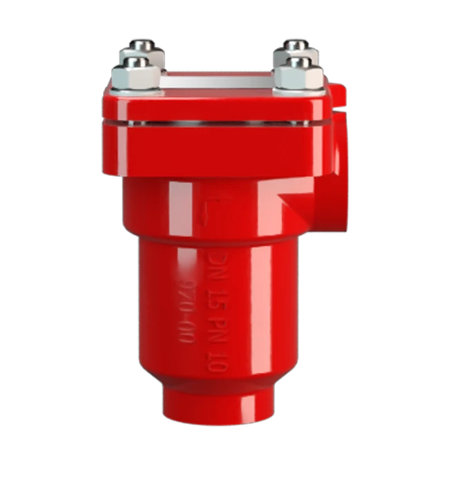
Features
Diseño compacto
Número reducido de discos FLAMEFILTER®
Montaje y desmontaje más rápido
Seguridad frente a explosiones
Cuerpo angular
Protección de última generación
Piezas de recambio
Bajo coste
Protege contra deflagraciones y detonaciones estables

Componente Principal: Apagallamas PROTEGO®

Muchas certificaciones individuales
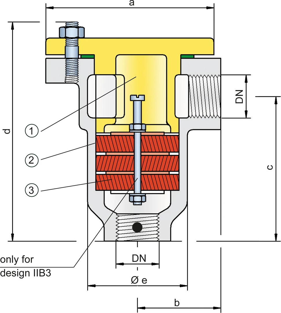
Dimensiones
Para seleccionar el tamaño nominal (DN), se ruega utilizar los diagramas de flujo volumétrico de las páginas siguientes
| DN | G ¼" | G ½" | G ¾" |
| a | 48 / 1.89 | 70 / 2.76 | 80 / 3.15 |
| b | 35 / 1.38 | 40 / 1.57 | 47 / 1.85 |
| c | 70 / 2.76 | 75 / 2.95 | 87 / 3.43 |
| d | 108 / 4.25 | 115 / 4.53 | 135 / 5.31 |
| e | 34 / 1.34 | 50 / 1.97 | 60 / 2.36 |
Dimensiones en mm / pulgadas
Selección del grupo de explosión
| MESG | Gr. Expl. (IEC / CEN) | Grupo de gas (NEC) |
| ≥ 0,65 mm | IIB3 | C |
| < 0,50 mm | IIC | B |
Homologaciones especiales bajo demanda
Selección de la máxima presión de operación
| Gr. Expl. | DN | G ¼" | G ½" | G ¾" |
| IIB3 | Pmáx | 1,2 / 17.4 | 1,2 / 17.4 | 1,2 / 17.4 |
| IIC | Pmáx | 1,1 / 15.9 | 1,1 / 15.9 | 1,1 / 15.9 |
Pmáx = máxima presión de operación admisible en bar / psi (absoluto),
presiones de operación más altas bajo demanda Gr. expl. IIB3 cubre Gr. expl. IIA
Especificación de la máx. temperatura de operación
| ≤ 60°C / 140°F | Tmáx - Temperatura máxima de operación admisible en °C |
| - | Designation |
Temperaturas de operación más altas bajo demanda
Selección de materiales para la vivienda
| Diseño | B | C | D |
| Cuerpo | Acero | Acero inox | Hastelloy |
| Cubierta c. reduct choque* | Acero | Acero inox | Hastelloy |
| Junta | PTFE | PTFE | PTFE |
| Unidad apagallamas | A | A | B |
G ¼" sólo existe en diseño C y D
* G ¼" sin reductor de choque
Materiales especiales bajo demanda
Combinación de materiales para la unidad apagallamas
| Diseño | A | B |
| FLAMEFILTER®* | Acero inox | Hastelloy |
| Espaciador | Acero inox | Hastelloy |
* Los discos de filtro FLAMEFILTER® también están disponibles en tántalo, inconel, cobre, etc. Cuando se usan los materiales del cuerpo y la jaula del listado.
Materiales especiales bajo demanda
Tipo de conexión
| Rosca tubería DIN ISO 228-1 | DIN |
Otros tipos de rosca bajo demanda
Diagrama de flujo volumétrico
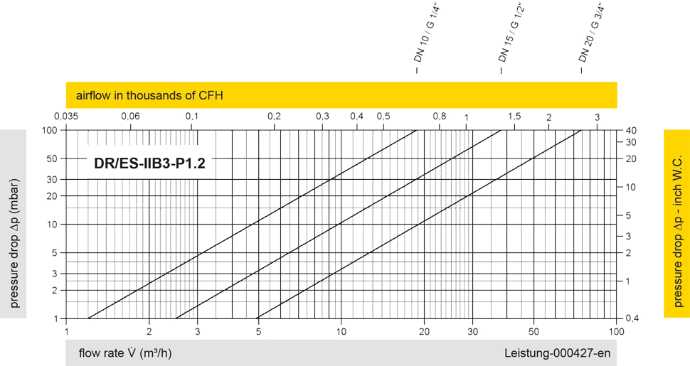
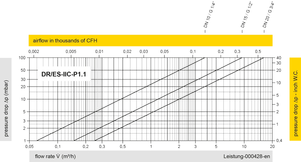
Los diagramas de flujo volumétrico han sido determinados con un banco de pruebas de caudal calibrado y certifi - cado por TÜV. El flujo volumétrico V. en [m³/h] y el CFH se refi eren a las condiciones estándar de referencia de aire según ISO 6358 (20°C, 1bar). La conversión a otras densidades y temperaturas están referidas en el Vol. 1: “Fundamentos Técnicos”.


Si tienes alguna pregunta, comentario o sugerencia, nuestro equipo de expertos estará encantado de ayudarte.
