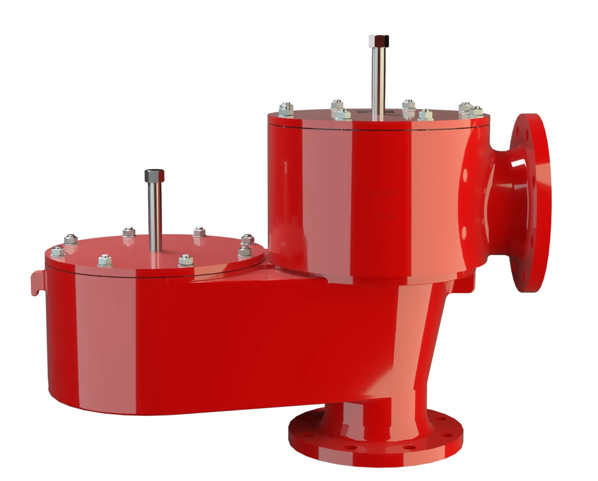
VD/SV-PA(L)
Pressure and Vacuum Relief Valve with pipe-away connection
Features
10% Technology
Extreme Tightness
Optimum Pressure Maintenance
Flow Capacity
Used in Explosion Hazardous Areas
Condensate Drainage
API Tanks
Combined Pressure and Vacuum Relief Valve

Full Lift Technology
Advanced Manufacturing Technology
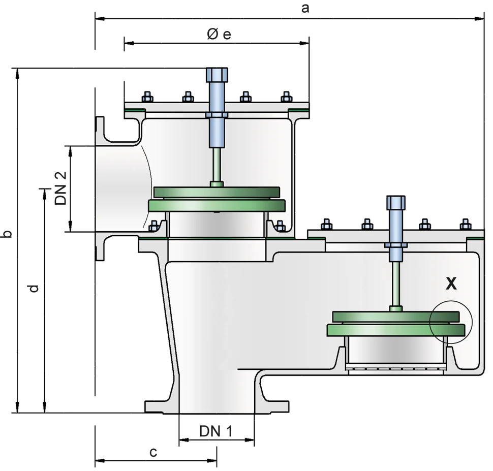
Dimensiones
To select the nominal size Nominal size The nominal size is an alphanumeric designation of size for components in a piping system, used for reference purposes, comprising the letters DN followed by a dimensionless integer that is indirectly related to the physical size of the bore or outside diameter of the connections, expessed in millimeters. (DN), use the flow capacity charts on the following pages
| VD / SV-PA | |||||||
| DN 1 | 50 / 2" | 80 / 3" | 100 / 4" | 150 / 6" | 200 / 8" | 250 / 10" | 300 / 12" |
| DN 2 | 50 / 2" | 80 / 3" | 100 / 4" | 150 / 6" | 200 / 8" | 250 / 10" | 300 / 12" |
| a | 405 / 15.95 | 480 / 18.90 | 600 / 23.62 | 805 / 31.69 | 925 / 36.42 | 1010 / 39.76 | 1010 / 39.76 |
| b | 390 / 15.35 | 485 / 19.09 | 550 / 21.65 | 660 / 25.98 | 780 / 30.71 | 875 / 34.45 | 875 / 34.45 |
| c | 150 / 5.91 | 180 / 7.09 | 200 / 7.87 | 250 / 9.84 | 300 / 11.81 | 305 / 12.01 | 305 / 12.01 |
| d | 240 / 9.45 | 300 / 11.81 | 330 / 12.99 | 390 / 15.35 | 480 / 18.90 | 555 / 21.85 | 582 / 22.91 |
| e | 165 / 6.50 | 192 / 7.56 | 240 / 9.45 | 350 / 13.78 | 390 / 15.35 | 460 / 18.11 | 460 / 18.11 |
| VD / SV-PAL | |||||||
| DN 1 | 50 / 2" | 80 / 3" | 100 / 4" | 150 / 6" | 200 / 8" | 250 / 10" | 300 / 12" |
| DN 2 | 80 / 3" | 100 / 4" | 150 / 6" | 200 / 8" | 250 / 10" | 300 / 12" | 350 / 14" |
| a | 395 / 15.55 | 445 / 17.52 | 565 / 22.24 | 770 / 30.31 | 895 / 35.24 | 1010 / 39.76 | 1010 / 39.76 |
| b | 400 / 15.74 | 485 / 19.09 | 550 / 21.65 | 655 / 25.79 | 775 / 30.51 | 875 / 34.45 | 885 / 34.84 |
| c | 140 / 5.51 | 143 / 5.63 | 165 / 6.50 | 216 / 8.50 | 267 / 10.51 | 305 / 12.01 | 305 / 12.01 |
| d | 255 / 10.04 | 308 / 12.13 | 355 / 13.98 | 417 / 16.42 | 505 / 19.88 | 582 / 22.91 | 603 / 23.74 |
| e | 165 / 6.50 | 192 / 7.56 | 240 / 9.45 | 350 / 13.78 | 390 / 15.35 | 460 / 18.11 | 460 / 18.11 |
Dimensiones en mm / pulgadas
Dimensions of pressure and vacuum relief valves with heating jacket upon request
Selección de materiales para la vivienda
| Design | A | B | C |
| Housing Housing A housing is a solid shell, which surrounds a content, either protecting the content from external influences, or protecting the environment from the content. | Aluminium | Steel | Stainless Steel |
| Heating jacket (VD / SV-PA(L)-H-...) | – | Steel | Stainless Steel |
| Valve seat Valve seat The valve seat is a component on which the valve pallet rests when the valve is closed. | Stainless Steel | Stainless Steel | Stainless Steel |
| Sealing | PTFE | PTFE | PTFE |
Option: Housing with ECTFE- lining Lining Protective plastic lining with a defined minimum/maximum thickness to protect against aggressive mixtures (e.g., acid).
Special materials upon request
Selección de materiales para la válvula de presión
| Design | A | B | C | D | E | F |
| Pressure range [mbar] [inch W.C.] | +2,0 up to +3,5 +0.8 up to +1.4 | >+3,5 up to +14 >+1.4 up to +5.6 | >+14 up to +35 >+5.6 up to +14 | >+35 up to +60 >+14 up to +24 | >+14 up to +35 >+5.6 up to +14 | >+35 up to +60 >+14 up to +24 |
| Valve pallet | Aluminium | Stainless Steel | Stainless Steel | Stainless Steel | Stainless Steel | Stainless Steel |
| Sealing | FEP | FEP | Metal to Metal | Metal to Metal | PTFE | PTFE |
Special materials as well as higher set pressure upon request
Selección de materiales para la válvula de vacío
| Design | A | B | C | D | E | F |
| Pressure range [mbar] [inch W.C.] | -2,0 up to -3,5 -0.8 up to -1.4 | <-3,5 up to -14 <-1.4 up to -5.6 | <-14 up to -35 <-5.6 up to -14 | <-14 up to -35 <-5.6up to -14 | <-35 up to -60 <-14 up to -24 | <-35 up to -60 <-14 up to -24 |
| Valve pallet | Aluminium | Stainless Steel | Stainless Steel | Stainless Steel | Stainless Steel | Stainless Steel |
| Sealing | FEP | FEP | Metal to Metal | Metal to Metal | PTFE | PTFE |
Special material as well as higher set vacuum upon request
Tipo de bridas de conexión
| EN 1092-1; Form B1 |
| ASME B16.5 CL 150 R.F. |
other types upon request
Diagrama de flujo volumétrico
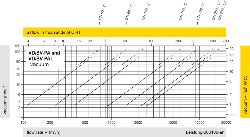
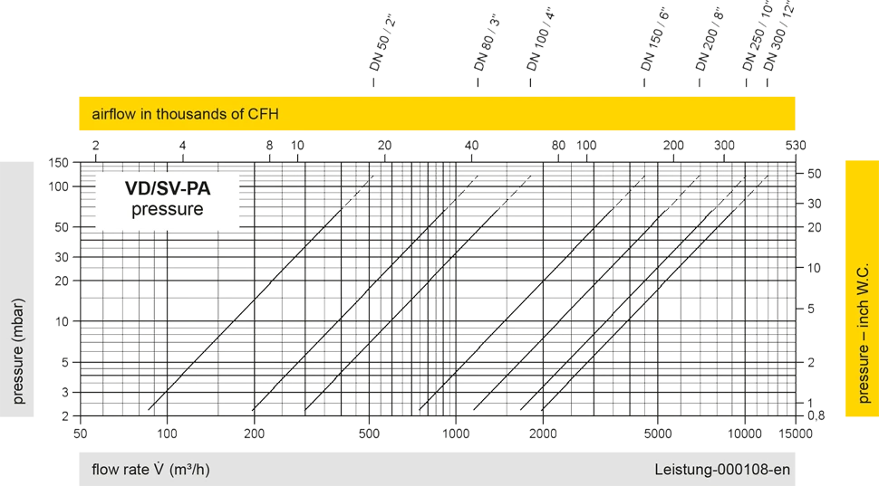
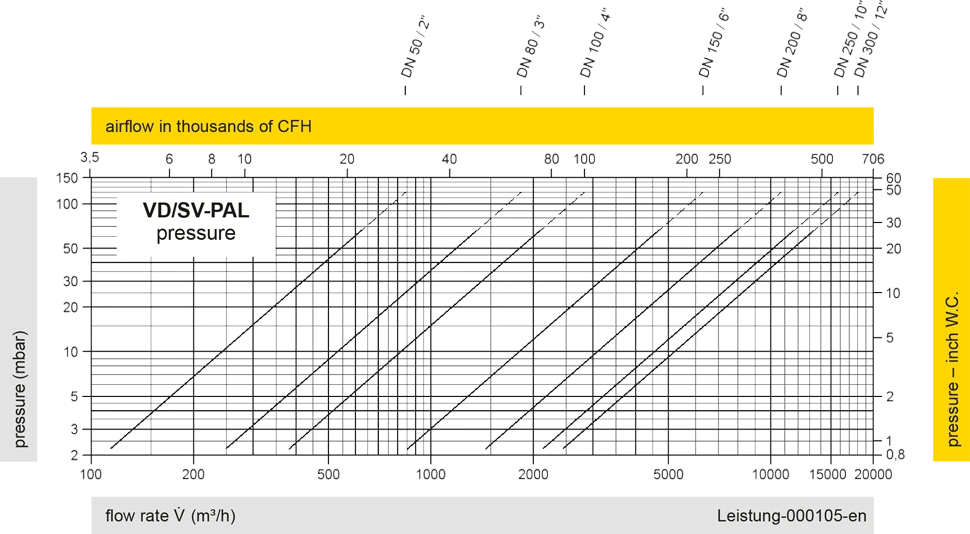
Los diagramas de flujo volumétrico han sido determinados con un banco de pruebas de caudal calibrado y certifi - cado por TÜV. El flujo volumétrico V. en [m³/h] y el CFH se refi eren a las condiciones estándar de referencia de aire según ISO 6358 (20°C, 1bar). La conversión a otras densidades y temperaturas están referidas en el Vol. 1: “Fundamentos Técnicos”.
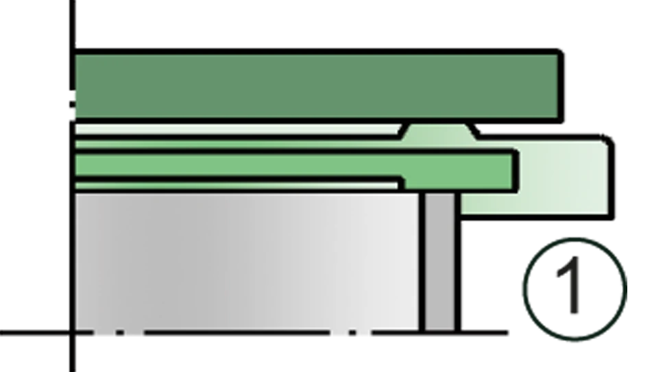
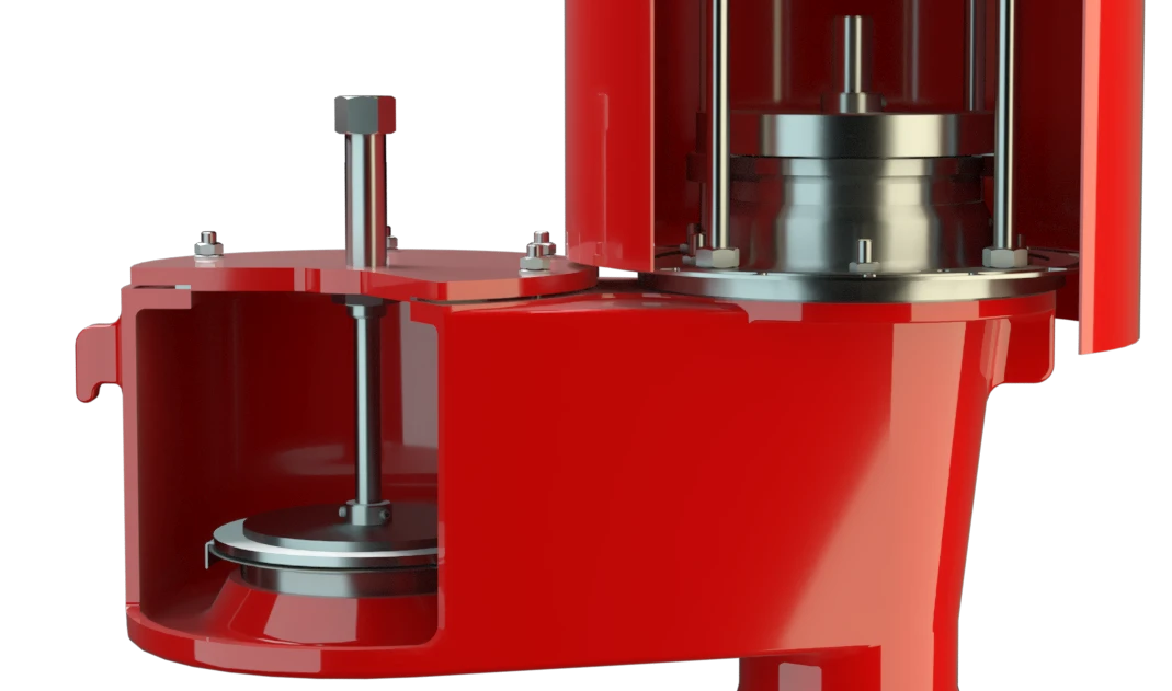
Detail X
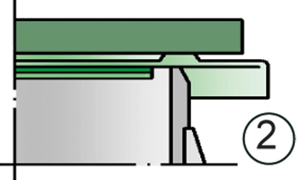
Detail X


Si tienes alguna pregunta, comentario o sugerencia, nuestro equipo de expertos estará encantado de ayudarte.
