DE/S-IIB3
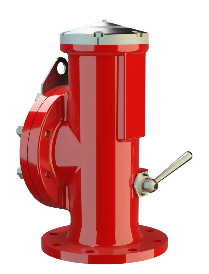
High Velocity Pressure Relief Valve deflagration- and endurance burning-proof
Features
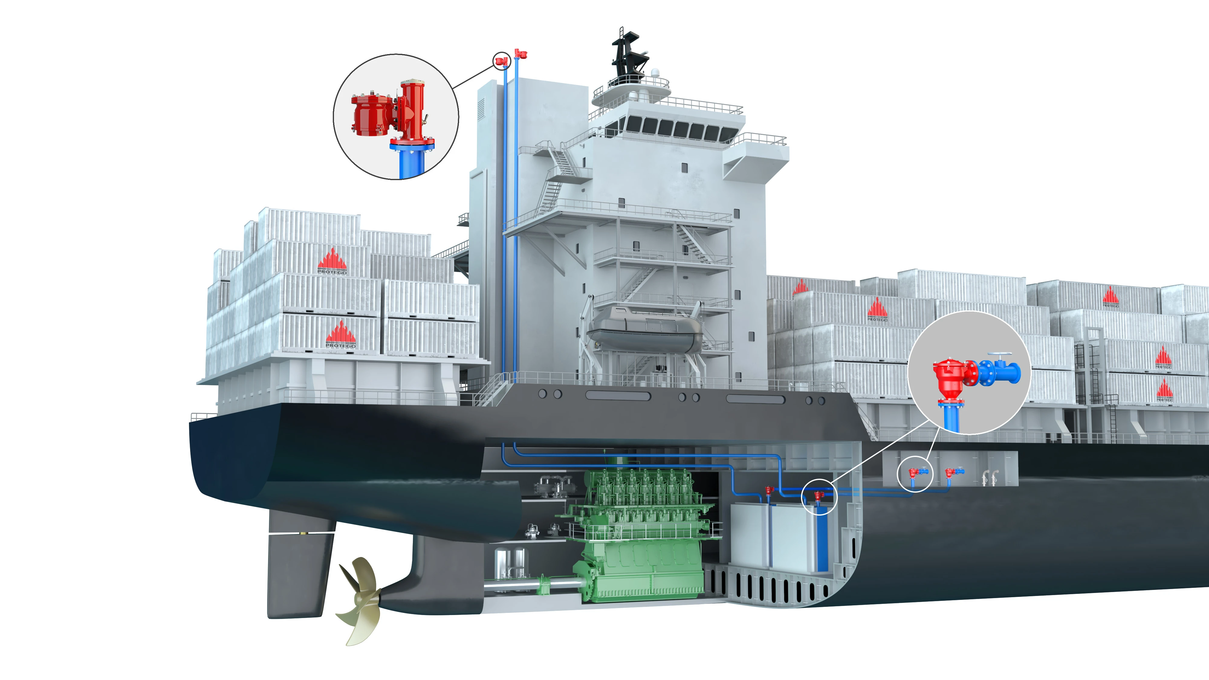
In Land Water Way Barges
Pop-Open Characteristic
Extreme Tightness
Optimal Pressure Maintenance
Protective System According to ATEX
Safety Against Endurance Burning
Flow Capacity
Permanent Magnets
High-Speed Pressure Relief Valve
Jump Characteristic

Advanced Manufacturing Technology
Dynamic Flame Arresting Safety in Overpressure Relief Valves

Many Individual Certifications
Dimensiones
To select the nominal size Diámetro nominal The nominal size is an alphanumeric designation of size for components in a piping system, used for reference purposes, comprising the letters DN followed by a dimensionless integer that is indirectly related to the physical size of the bore or outside diameter of the connections, expessed in millimeters. (DN), please use the flow capacity chart on the following page
| DE / S with closed lateral connection DN 2 | ||||
| DN 1 | 80 / 3" | 100 / 4" | 150 / 6" | |
| a | 515 / 20.28 | 515 / 20.28 | 515 / 20.28 | |
| b | 195 / 7.68 | 195 / 7.68 | 195 / 7.68 | |
| c | 220 / 8.66 | 220 / 8.66 | 220 / 8.66 | |
| d | 120 / 4.72 | 120 / 4.72 | 120 / 4.72 | |
| e1 | 145 / 5.71 | 145 / 5.71 | 145 / 5.71 | |
| DE / S with lateral connection for vacuum relief valve Válvula de vacío A vacuum relief valve is used to ventilate a part of the system and protects it from impermissible underpressure. DN 2 | ||||
| DN 1 | 80 / 3" | 100 / 4" | 150 / 6" | 150 / 6" |
| DN 2 | 80 / 3" | 80 / 3" | 80 / 3" | 150 / 6" |
| a | 515 / 20.28 | 515 / 20.28 | 515 / 20.28 | 515 / 20.28 |
| b | 195 / 7.68 | 195 / 7.68 | 195 / 7.68 | 195 / 7.68 |
| c | 220 / 8.66 | 220 / 8.66 | 220 / 8.66 | 220 / 8.66 |
| d | 120 / 4.72 | 120 / 4.72 | 120 / 4.72 | 120 / 4.72 |
| e2 | 100 / 3.94 | 100 / 3.94 | 100 / 3.94 | 100 / 3.94 |
Dimensiones en mm / pulgadas
Selección del grupo de explosión
| MESG | Expl. Gr. (IEC / CEN) | Gas Group (NEC) |
| ≥ 0,65 mm | IIB3 | C |
Special approvals upon request
Selección de materiales
| Design | A | B | D |
| Housing | Steel | Stainless Steel | Hastelloy |
| Valve seat | Stainless Steel | Stainless Steel | Hastelloy |
| Valve cone | Stainless Steel | Stainless Steel | Hastelloy |
| Bellow | PTFE | PTFE | PTFE |
| Gasket | PTFE | PTFE | PTFE |
Special materials upon request
Tipo de bridas de conexión
| EN 1092-1; Form B1 |
| ASME B16.5 CL 150 R.F. |
other types upon request
Diagrama de flujo volumétrico
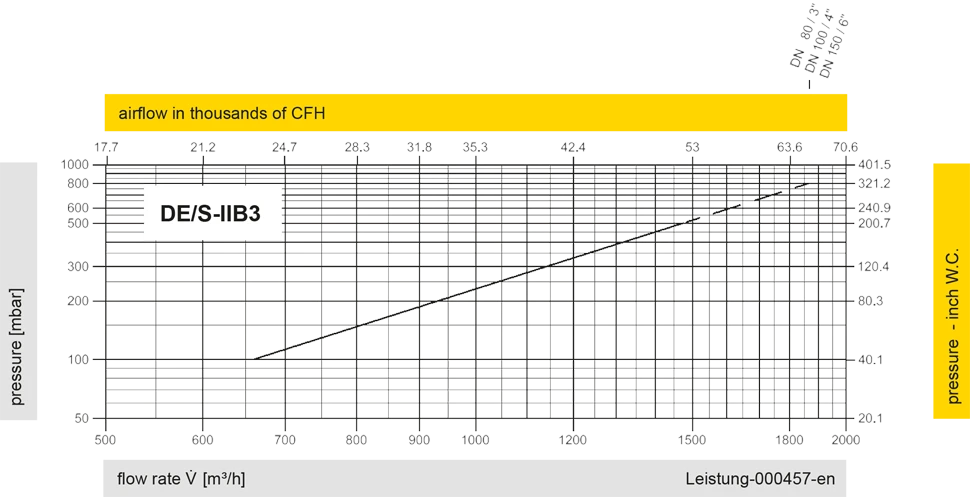
Los diagramas de flujo volumétrico han sido determinados con un banco de pruebas de caudal calibrado y certifi - cado por TÜV. El flujo volumétrico V. en [m³/h] y el CFH se refi eren a las condiciones estándar de referencia de aire según ISO 6358 (20°C, 1bar). La conversión a otras densidades y temperaturas están referidas en el Vol. 1: “Fundamentos Técnicos”.
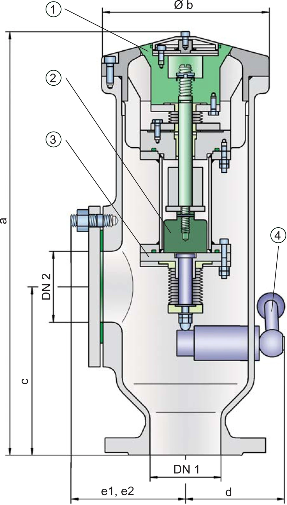
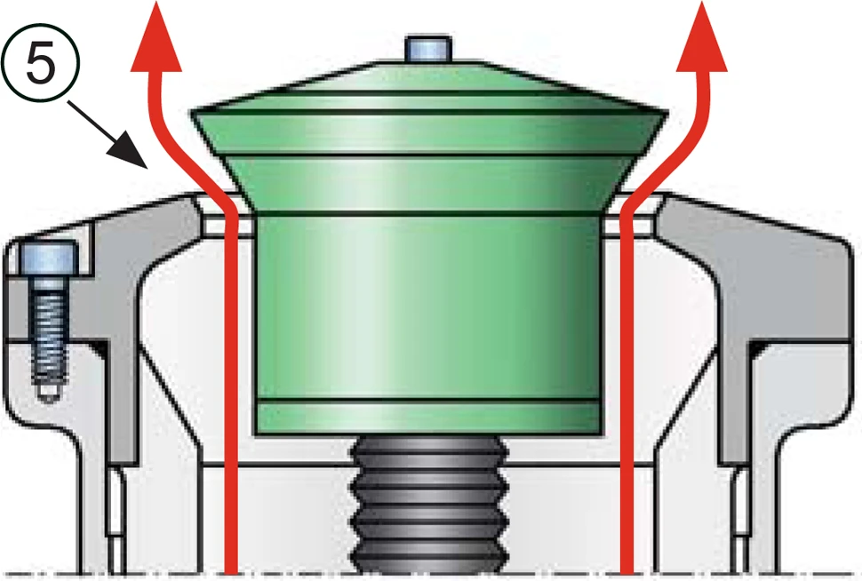
operating position of valve - open


Si tienes alguna pregunta, comentario o sugerencia, nuestro equipo de expertos estará encantado de ayudarte.
