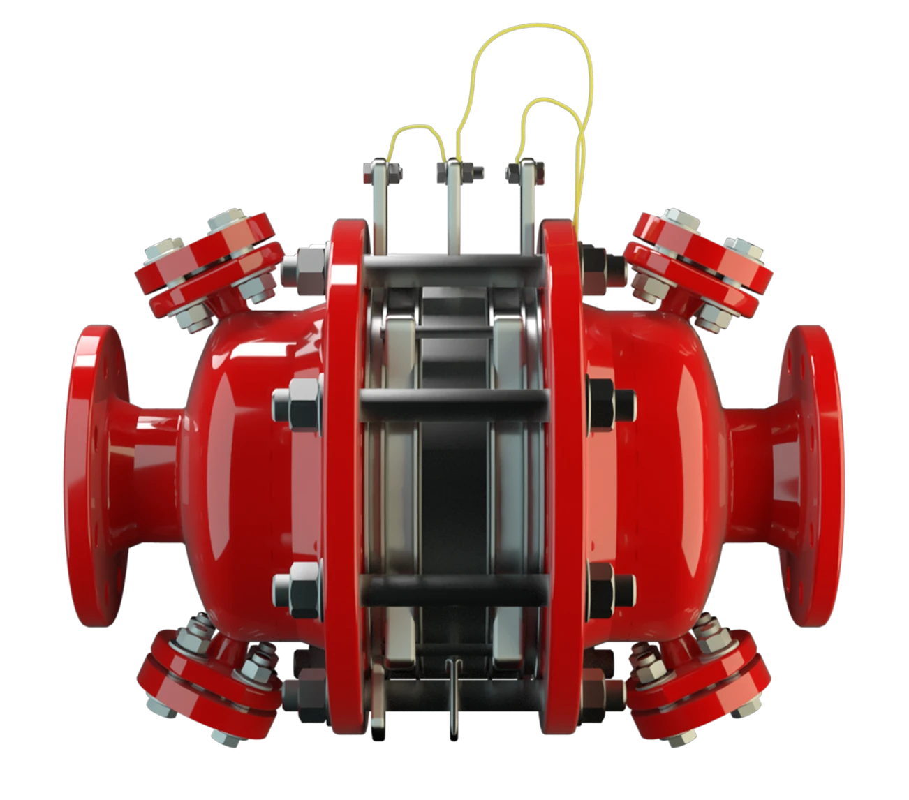
DA-SB-PTFE
In-Line Detonation Flame Arrester for stable detonations and deflagrations in a straight through design with shock absorber, bidirectional
Features
Bajo coste
Posibilidad de instalar sensores de temperatura
Transmisión bidireccional de la llama
Diseño modular
Diferentes series
Productos agresivos, pegajosos o polimerizantes
Uso del efecto patentado del tubo guía de ondas de choque (SWGTE)
High-Tech Coating of the Housing

Main Component – PROTEGO® Flame Arrester Unit

For Explosion Group IIA
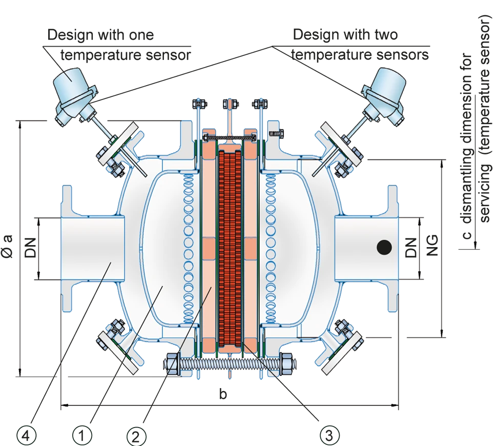
Dimensiones
To select nominal width/nominal size (NG/DN) - combination, please use the flow capacity chart on the following pages
| NG | 150 / 6" | 150 / 6" | 200 / 8" | 300 / 12" |
| DN | 50 / 2" | 80 / 3" | 80 / 3" | 100 / 4" |
| a | 287 / 11.30 | 287 / 11.30 | 342 / 13.46 | 447 / 17.60 |
| b | 407 / 15.75 | 407 / 15.75 | 497 / 19.57 | 645 / 25.39 |
| c | 400 / 15.75 | 400 / 15.75 | 530 / 20.87 | 530 / 20.87 |
Dimensiones en mm / pulgadas
Selección del grupo de explosión
| MESG | Expl. Gr. (IEC / CEN) | Gas Group (NEC) |
| > 0,90 mm | IIA | D |
Special approvals upon request
Selección de la máxima presión de operación
| NG | 150 / 6" | 150 / 6" | 200 / 8" | 300 / 12" |
| DN | 50 / 2" | 80 / 3" | 80 / 3" | 100 / 4" |
| Pmax | 2,4 / 34.8 | 1,1 / 15.9 | 1,2 / 17.4 | 1,2 / 17.4 |
Pmax = Maximum allowable operating pressure in bar / psi absolut, higher operating pressure upon request
Especificación de la máx. temperatura de operación
| ≤ 60°C / 140°F | Tmaximum allowable operating temperature in °C |
| - | Designation |
higher operating temperatures upon request
Material for housing
| Design | A |
| Housing | Steel with an ECTFE coating |
| Shock absorber | Steel with an ECTFE coating |
| Gasket | PTFE |
| Flame arrester unit Flame arrester unit Flame arrester casing with FLAMEFILTER® set. | A, B, C |
Special materials upon request
Combinación de materiales para la unidad apagallamas
| Design | A | B | C |
| FLAMEFILTER® cage | Steel with an ECTFE coating | Hastelloy | Stainless Steel |
| Spider rings | Steel with an ECTFE coating | Hastelloy | Stainless Steel |
| FLAMEFILTER®* | PTFE* | PTFE* | PTFE* |
| Spacer Spacer The spacer is a component that is generally used in a PROTEGO® flame arrester as a spacer within the FLAMEFILTER® se | PEEK / ETFE / FEP | PEEK / ETFE / FEP | PEEK / ETFE / FEP |
* electrically conductive
Special materials upon request
Tipo de bridas de conexión
| EN 1092-1; Form B1 |
| ASME B16.5 CL 150 R.F. |
other connections upon request
Diagrama de flujo volumétrico
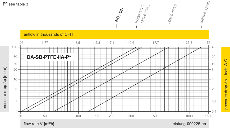
Los diagramas de flujo volumétrico han sido determinados con un banco de pruebas de caudal calibrado y certifi - cado por TÜV. El flujo volumétrico V. en [m³/h] y el CFH se refi eren a las condiciones estándar de referencia de aire según ISO 6358 (20°C, 1bar). La conversión a otras densidades y temperaturas están referidas en el Vol. 1: “Fundamentos Técnicos”.


Si tienes alguna pregunta, comentario o sugerencia, nuestro equipo de expertos estará encantado de ayudarte.
