Features
For Cyrogen Tanks
Suitable for Use on Cryogen Tanks
Fail-Safe-Concept
In Event of an Energy Drop, the Valve Piston Seals the Outlet Line by its own Weight
API 625
These Devices meet the Requirements of API 625
Tightness
Good Tightness of the Valve
Emergency Cable in Case of Damage
An Emergency Cable Opens the Valve if the Main Cable is Damaged
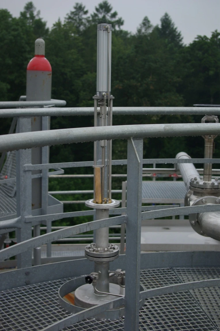
Pneumatic Cylinder
Devices Are Kept Open by a Pneumatic Cylinder
Function and Description
Quick-Release Bottom Drain Valves for Cryogenic Storage Tanks
PROTEGO® NB/AP
Pressure/vacuum relief valve
Pressure/vacuum relief valve is an umbrella term that includes pressure or vacuum relief valve as well as pressure and vacuum relief valve.
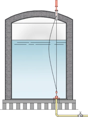
In-Tank Valves are used in storage tanks for cryogenic liquids in order to
seal
Seal
A seal prevents or limits unwanted transfer of product from one container to another. Seal is used as superordinate term for all types of sealing elements.
off discharge lines in the event of an accident or emergency (pipe bursting). These devices meet the Requirements of API 625.
Tightness by a Lapped Metallic Valve Pallet and Relief Valve Cone
The
device
Device
A device is a pipe component that influences the media flow by opening, closing, or partially shutting off the flow channel or by dividing or mixing the media flow.
consists of the
bottom plate
Bottom plate
A bottom plate forms the foundation inside a tank for the installation of tank accessories, e. g. suction units or tank valves.
(1) which has to be welded onto the
vessel
Vessel
Container or structural envelope in which materials are processed, treated or stored.
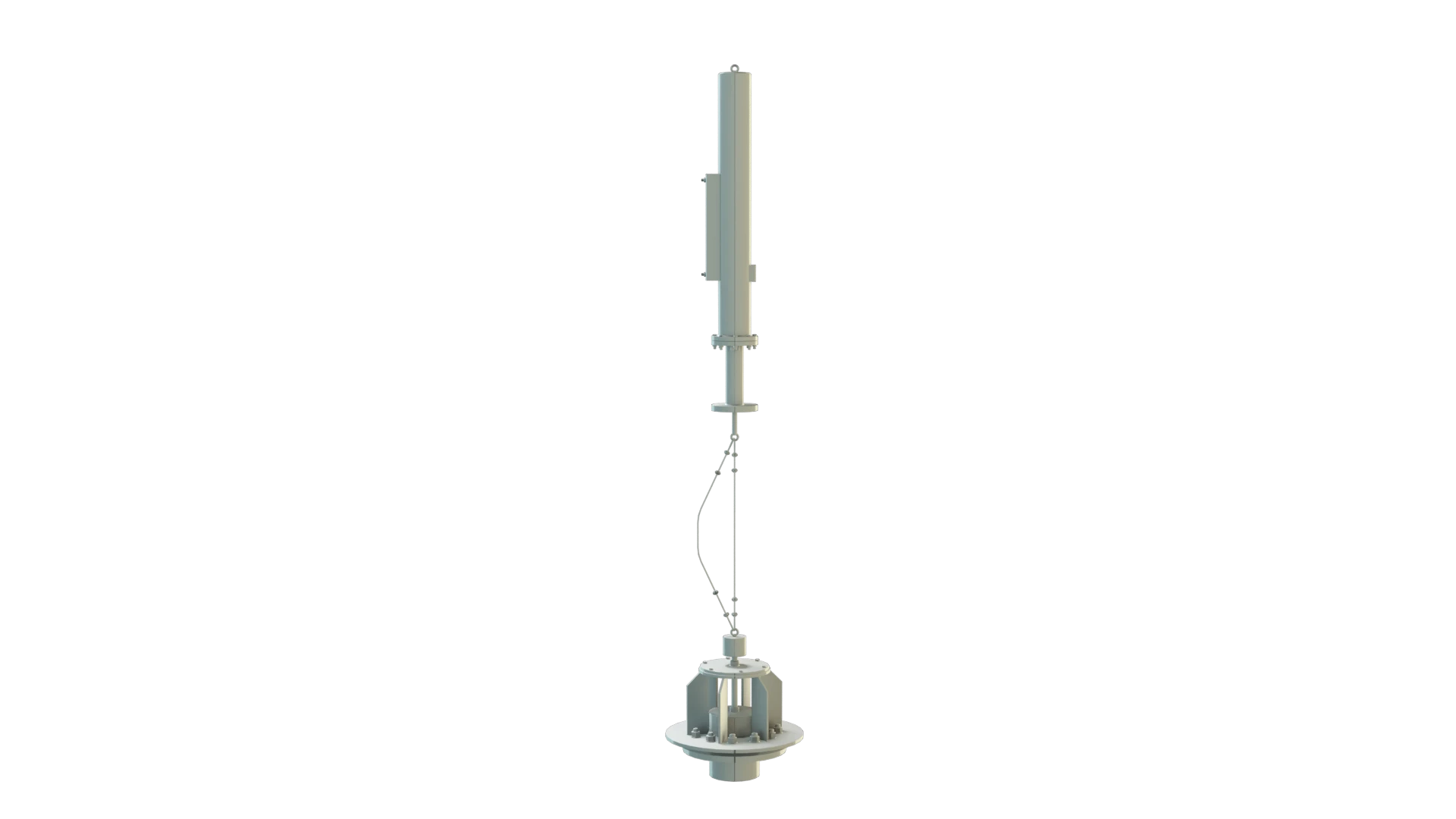
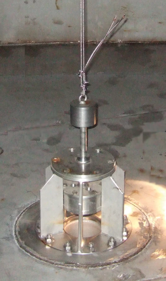
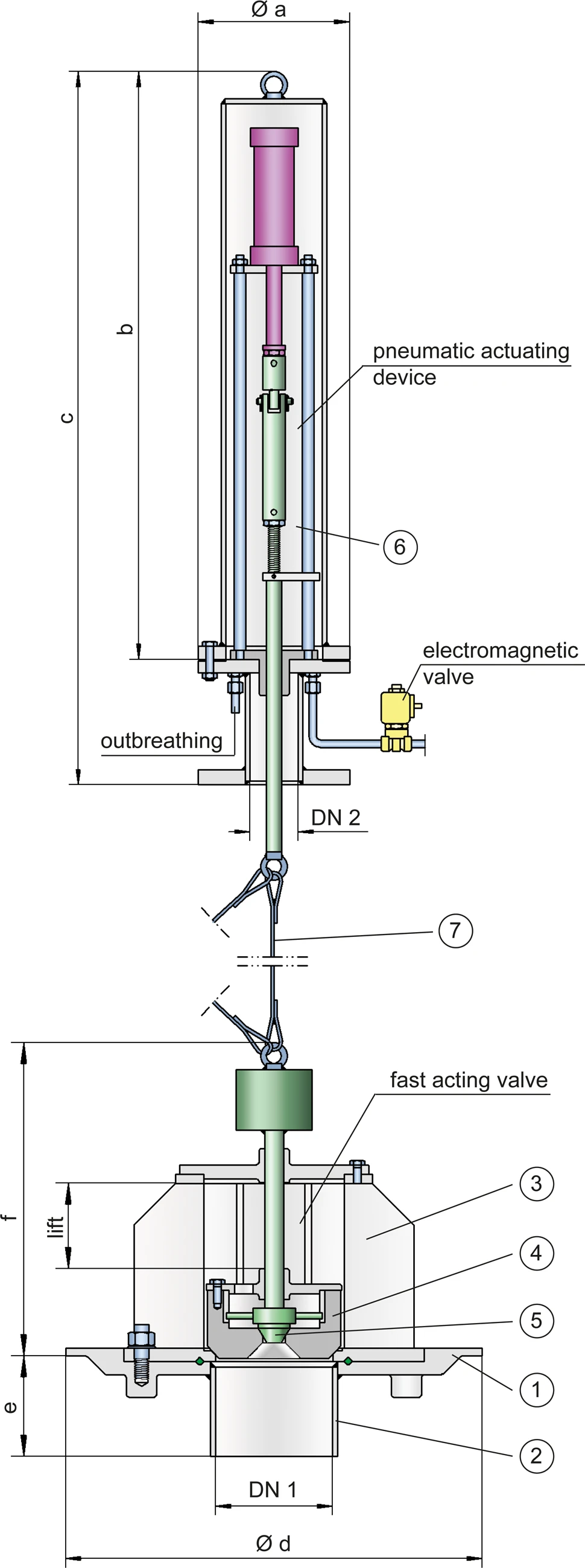
bottom; a nozzle (2) which has to be welded to the discharge line; the flanged fast-acting valve (3) with valve piston (4) and release valve cone (5); and the complete pneumatic actuating device (6) which is mounted onto the roof of the tank. The required tightness is ensured by a lapped metallic
valve pallet
Valve pallet
Valve pallet is the generic term for the assembly that rests on the valve seat.
and relief valve cone. The quick-release valve (3) and the actuating system (6) are connected by an actuator cable (7). An additional emergency cable enables the quick-release valve to be opened if the main actuator rope is damaged.
Fail-Safe-Concept
During normal operation, a pneumatic cylinder holds the valves in the open position. The pneumatic cylinder is actuated by a control line to
lift
Lift
Lift is the actual travel of the valve pallet from the main valve out of the closed position.
the valve piston. The bottom valve is only closed in an emergency. In the event of an energy drop, the valve piston, due to its own weight, falls onto the
valve seat
Valve seat
The valve seat is a component on which the valve pallet rests when the valve is closed.
which closes the bottom valve.(Fail Safe Concept).
Customized Solutions for Specific Plant Requirements
The valve design is independent of the
nominal size
Nominal size
The nominal size is an alphanumeric designation of size for components in a piping system, used for reference purposes, comprising the letters DN followed by a dimensionless integer that is indirectly related to the physical size of the bore or outside diameter of the connections, expessed in millimeters.
. The nominal size DN 1 is determined by the nominal size of discharge line. Material selection depends on the substance and the
operating temperature
Operating temperature
Temperature reached when the equipment is operating under design conditions.
.
Product Data
Dimensiones
| DN 1 | DN 2 | a | b | c | d | e | f | Hub |
| 150 / 6" | 80 / 3" | 200 / 7.87 | 1130 / 44.49 | 1430 / 56.30 | 550 / 21.65 | 175 / 6.89 | 465 / 18.31 | 160 / 6.30 |
| 200 / 8" | 80 / 3" | 200 / 7.87 | 1130 / 44.49 | 1430 / 56.30 | 600 / 23.62 | 175 / 6.89 | 470 / 18.50 | 160 / 6.30 |
| 250 / 10“ | 80 / 3" | 200 / 7.87 | 1130 / 44.49 | 1430 / 56.30 | 740 / 29.13 | 175 / 6.89 | 485 / 19.09 | 160 / 6.30 |
Dimensiones en mm / pulgadas
Material of fast action bottom drain valve
| Bottom plate with nozzle | * |
| Valve housing Housing A housing is a solid shell, which surrounds a content, either protecting the content from external influences, or protecting the environment from the content. with valve cone | Stainless Steel |
| Gasket | * |
| Actuator rope | Stainless Steel |
* upon request
Material
| Housing | Stainless Steel |
| Actuator spindle | Stainless Steel |
| Guide bushing | Copper |
| Gasket | PTFE |
| Protective cap | Stainless Steel |
| Pneumatic cylinder | Aluminium |
Tipo de bridas de conexión
| EN 1092-1, Form B, PN 40 or upon request |
Applications
Si tienes alguna pregunta, comentario o sugerencia, nuestro equipo de expertos estará encantado de ayudarte.
