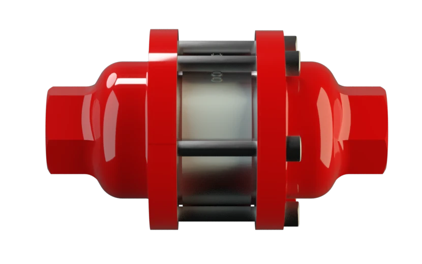
DA-G
In-Line Detonation Flame Arrester for stable detonations and deflagrations in a straight through design, bidirectional
Features
Diseño modular
Direccional
Montaje y desmontaje más rápido
Versatile Application Options
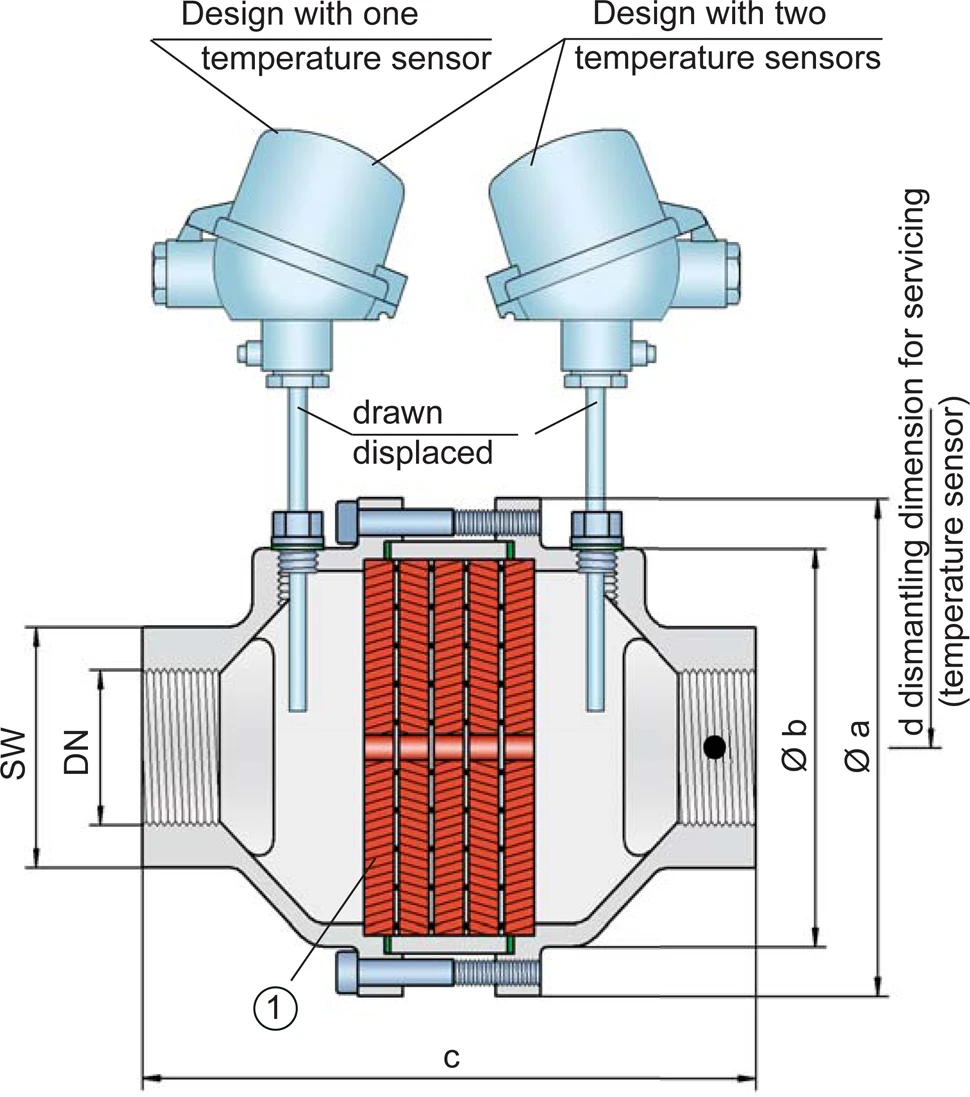
Posibilidad de instalar sensores de temperatura
Piezas de recambio
For Industrial Use in Gas Analysis Lines

Main Component – PROTEGO® Flame Arrester Unit

Many Individual Certifications
Dimensiones
To select the nominal size Nominal size The nominal size is an alphanumeric designation of size for components in a piping system, used for reference purposes, comprising the letters DN followed by a dimensionless integer that is indirectly related to the physical size of the bore or outside diameter of the connections, expessed in millimeters. (DN), please use the flow capacity charts on the following pages
| DN | G ½" | G ¾" | G 1" | G 1¼" | G 1½" | G 2" |
| a | 80 / 3.15 | 80 / 3.15 | 100 / 3.94 | 100 / 3.94 | 155 / 6.10 | 155 / 6.10 |
| b | 55 / 2.17 | 55 / 2.17 | 76 / 2.99 | 76 / 2.99 | 124 / 4.88 | 124 / 4.88 |
| c (IIA) | 112 / 4.41 | 112 / 4.41 | 122 / 4.80 | 122 / 4.80 | 205 / 8.07 | 205 / 8.07 |
| c (IIB3 and IIC) | 135 / 5.31 | 135 / 5.31 | 145 / 5.71 | 145 / 5.71 | 205 / 8.07 | 205 / 8.07 |
| d | — | — | — | — | 400 / 15.75 | 400 / 15.75 |
| SW | 32 / 1.26 | 32 / 1.26 | 50 / 1.97 | 50 / 1.97 | 75 / 2.95 | 75 / 2.95 |
Dimensions in mm / inches, SW= width across flats
Selección del grupo de explosión
| MESG | Expl. Gr. (IEC / CEN) | Gas Group (NEC) |
| > 0,90 mm | IIA | D |
| ≥ 0,65 mm | IIB3 | C |
| < 0,50 mm | IIC | B |
Special approvals upon request
Selección de la máxima presión de operación
| Expl. Gr. | DN | G ½" | G ¾" | G 1" | G 1¼" | G 1½" | G 2'' |
| IIA | Pmax | 1,2 / 17.4 | 1,2 / 17.4 | 1,1 / 15.9 | 1,1 / 15.9 | 1,1 / 15.9 | 1,1 / 15.9 |
| IIB3 | Pmax | 1,1 / 15.9 | 1,1 / 15.9 | 1,1 / 15.9 | 1,1 / 15.9 | 1,4 / 20.3 | 1,4 / 20.3 |
| IIC | Pmax | 1,1 / 15.9 | 1,1 / 15.9 | 1,1 / 15.9 | 1,1 / 15.9 | 1,6 / 23.2 | 1,6 / 23.2 |
Pmax = maximum allowable operating pressure in bar / psi absolute, higher operating pressure upon request
Especificación de la máx. temperatura de operación
| ≤ 60°C / 140°F | Tmaximum allowable operating temperature in °C |
| - | Designation |
higher operating temperatures upon request
Selección de materiales para la vivienda
| Design | B | C |
| Housing | Stainless Steel | Hastelloy |
| Gasket | PTFE | PTFE |
| FLAMEFILTER®* | Stainless Steel | Hastelloy |
* the FLAMEFILTER® are also available in the materials Tantalum, Inconel, Copper, etc. when the listed housing and cage materials are used.
Special materials upon request
Tipo de conexión
| Pipe thread DIN ISO 228-1 | DIN |
other types of thread upon request
Diagrama de flujo volumétrico
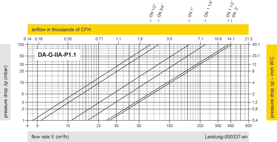
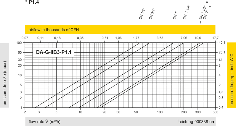
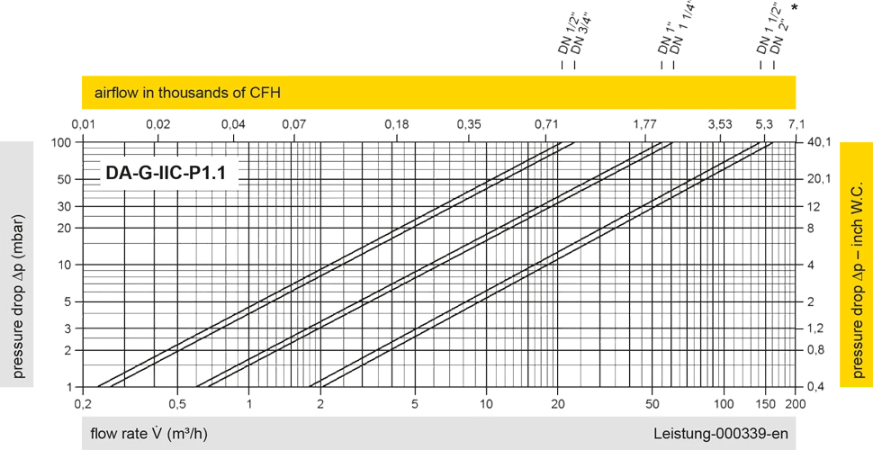
Los diagramas de flujo volumétrico han sido determinados con un banco de pruebas de caudal calibrado y certifi - cado por TÜV. El flujo volumétrico V. en [m³/h] y el CFH se refi eren a las condiciones estándar de referencia de aire según ISO 6358 (20°C, 1bar). La conversión a otras densidades y temperaturas están referidas en el Vol. 1: “Fundamentos Técnicos”.


Si tienes alguna pregunta, comentario o sugerencia, nuestro equipo de expertos estará encantado de ayudarte.
