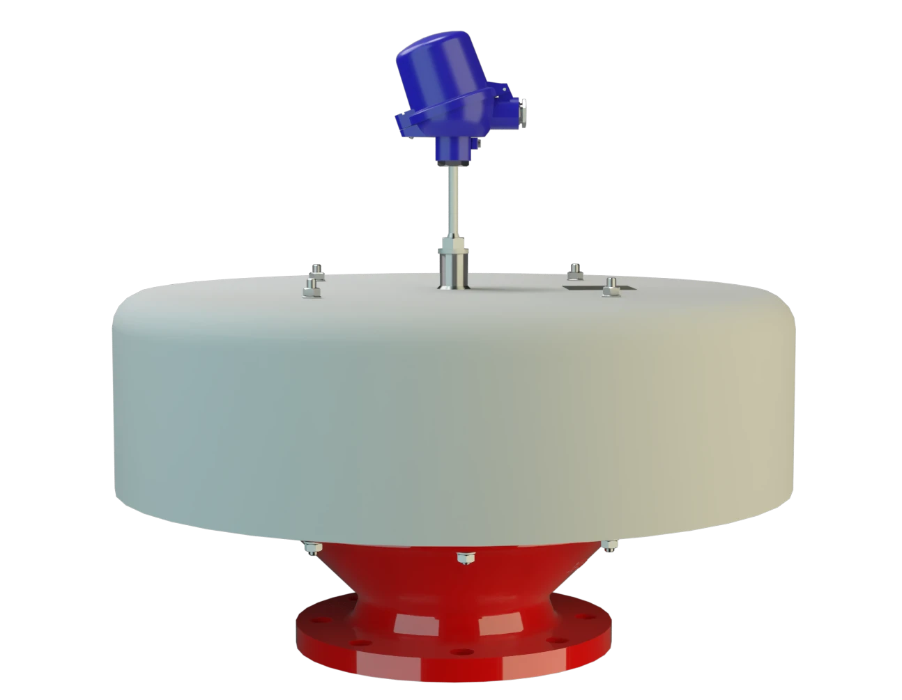
LH/AD-T
Deflagration Flame Arrester, short time burning-proof, End-of-Line
Features
Protección integral contra la intemperie
Varios tamaños
Fácil mantenimiento
Amplio rango de aplicaciones
Bajo coste
Piezas de recambio
Seguridad
Protection Against Atmospheric Deflagrations
Protection Against Short-Time Burning

Main Component – PROTEGO® Flame Arrester Unit

For Explosion Groups IIA to IIC
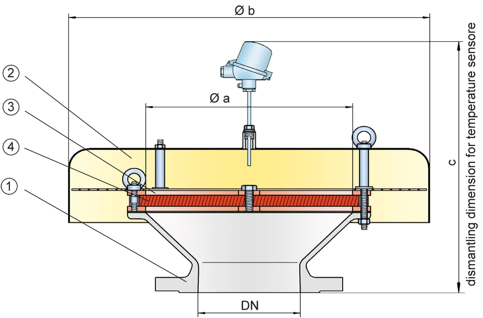
Dimensiones
To select the nominal size Nominal size The nominal size is an alphanumeric designation of size for components in a piping system, used for reference purposes, comprising the letters DN followed by a dimensionless integer that is indirectly related to the physical size of the bore or outside diameter of the connections, expessed in millimeters. (DN), please use the flow capacity charts on the following pages
| DN | a | b | c* | c* |
| IIB3 | IIC | |||
| 50 / 2" | 100 / 3.94 | 240 / 9.45 | 530 / 20.87 | 550 / 21.65 |
| 80 / 3" | 150 / 5.91 | 295 / 11.61 | 560 / 22.05 | 580 / 22.83 |
| 100 / 4" | 200 / 7.87 | 350 / 13.78 | 585 / 23.03 | 605 / 23.82 |
| 150 / 6" | 300 / 11.81 | 600 / 23.62 | 630 / 24.80 | 655 / 25.79 |
| 200 / 8" | 300 / 11.81 | 600 / 23.62 | 630 / 24.80 | 655 / 25.79 |
| 250 / 10" | 400 / 15.75 | 800 / 31.50 | 750 / 29.53 | 770 / 30.31 |
| 300 / 12" | 400 / 15.75 | 800 / 31.50 | 740 / 29.13 | 760 / 29.92 |
| 350 / 14" | 600 / 23.62 | 1000 / 39.37 | 800 / 31.50 | 820 / 32.28 |
| 400 / 16" | 600 / 23.62 | 1000 / 39.37 | 790 / 31.10 | 815 / 32.09 |
| 500 / 20" | 700 / 27.56 | 1200 / 47.24 | 810 / 31.89 | 835 / 32.87 |
| 600 / 24" | 800 / 31.50 | 1200 / 47.24 | 935 / 36.81 | 960 / 37.80 |
| 700 / 28" | 1000 / 39.37 | 1500 / 59.06 | 975 / 38.39 | 995 / 39.17 |
| 800 / 32" | 1200 / 47.24 | 1700 / 66.93 | 1015 / 39.96 | 1035 / 40.75 |
Dimensiones en mm / pulgadas
* c are reference values. Exact measures depend on the flange connection.
Selección del grupo de explosión
| MESG | Expl. Gr. (IEC / CEN) | Gas Group (NEC) |
| ≥ 0,65 mm | IIB3 | C |
| < 0,5 mm | IIC | B |
Special approvals upon request
Especificación de la máx. temperatura de operación
| ≤ 60°C / 140°F | Tmaximum allowable operating temperature in °C |
| - | Designation |
higher operating temperatures upon request
Selección de materiales para la vivienda
| Design | A | B |
| Housing | Steel | Stainless Steel |
| Weather Hood | Stainless Steel | Stainless Steel |
| Protection screen | Stainless Steel | Stainless Steel |
| Flame arrester unit Flame arrester unit Flame arrester casing with FLAMEFILTER® set. | A, B | B |
Special materials upon request
Combinación de materiales para la unidad apagallamas
| Design | A | B |
| FLAMEFILTER® cage | Steel | Stainless Steel |
| FLAMEFILTER® | Stainless Steel | Stainless Steel |
Special materials upon request
Tipo de bridas de conexión
| EN 1092-1; Form B1 |
| ASME B16.5 CL 150 R.F. |
other types upon request
Diagrama de flujo volumétrico
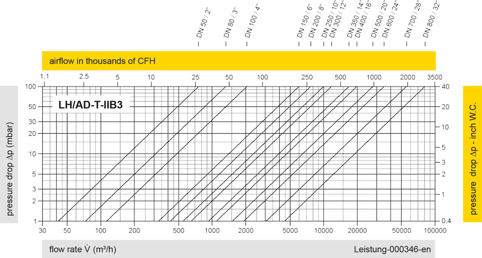
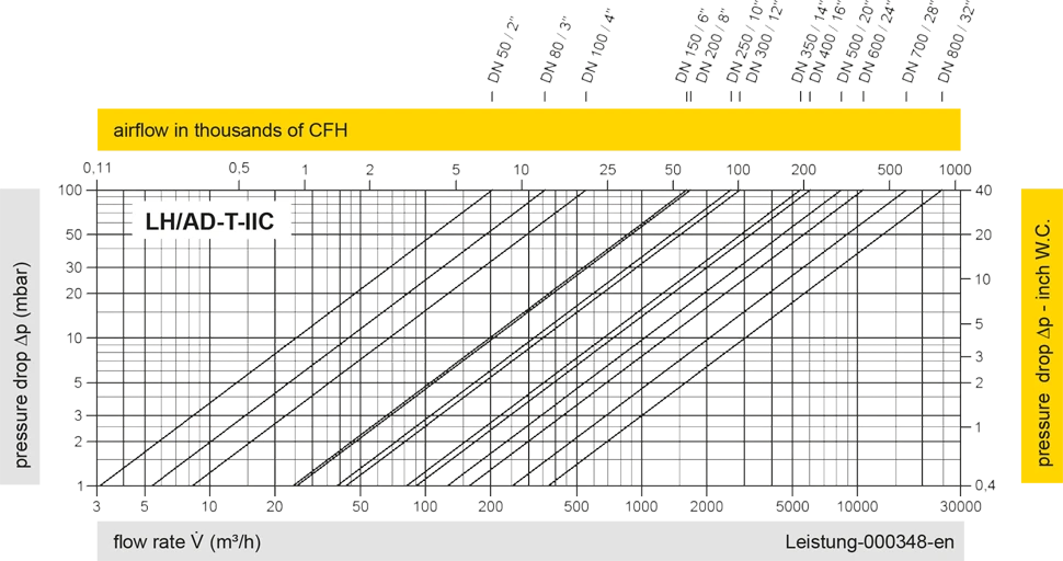
Los diagramas de flujo volumétrico han sido determinados con un banco de pruebas de caudal calibrado y certifi - cado por TÜV. El flujo volumétrico V. en [m³/h] y el CFH se refi eren a las condiciones estándar de referencia de aire según ISO 6358 (20°C, 1bar). La conversión a otras densidades y temperaturas están referidas en el Vol. 1: “Fundamentos Técnicos”.


Si tienes alguna pregunta, comentario o sugerencia, nuestro equipo de expertos estará encantado de ayudarte.
