EB
Deflagration Flame Arrester, endurance burning proof, End-of-Line
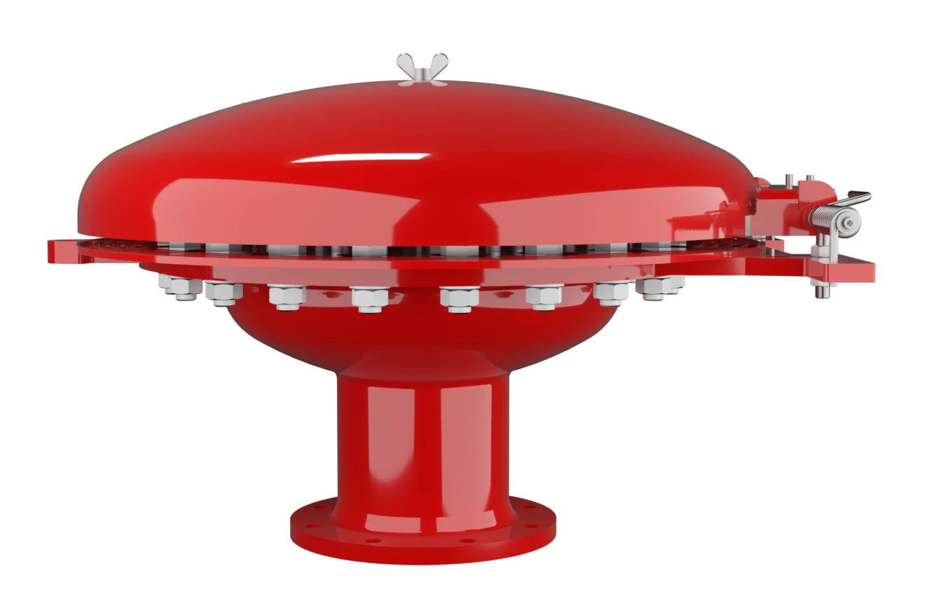
Features
Protección integral contra la intemperie
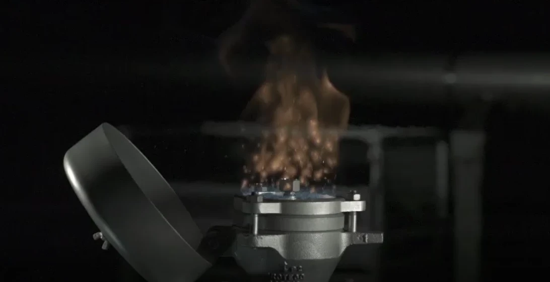
Indicación visible de fuego mediante inclinación de la caperuza protectora contra la intemperie
Seguridad frente a deflagraciones e incendios de hidrocarburos
Resistente a productos químicos
Diseño modular
Fácil mantenimiento
Piezas de recambio
Protection Against Atmospheric Deflagration and Endurance Burning
Main Component – PROTEGO® Flame Arrester Unit

For Explosion Group IIB and IIA
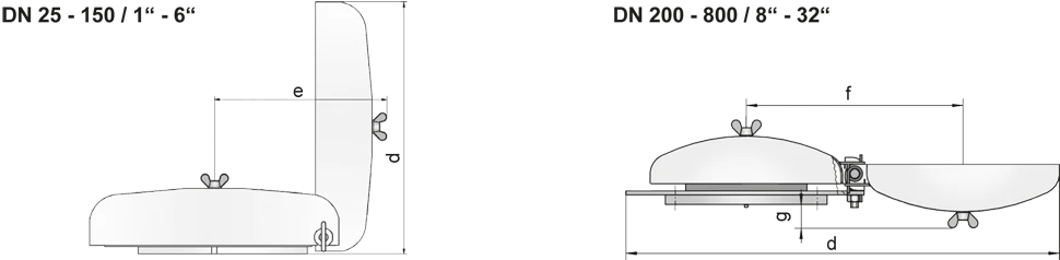
Dimensiones DN 25 - 150 para EB-IIA y IIB
To select the nominal size Nominal size The nominal size is an alphanumeric designation of size for components in a piping system, used for reference purposes, comprising the letters DN followed by a dimensionless integer that is indirectly related to the physical size of the bore or outside diameter of the connections, expessed in millimeters. (DN), please use the flow capacity chart on the following page
| DN | 25 / 1" | 32 / 1¼“ | 40 / 1½“ | 50 / 2“ | 65 / 2½“ | 80 / 3“ | 100 / 4" | 125 / 5" | 150 / 6" |
| a | 218 / 8.58 | 218 / 8.58 | 218 / 8.58 | 218 / 8.58 | 218 / 8.58 | 353 / 13.90 | 353 / 13.90 | 353 / 13.90 | 353 / 13.90 |
| b | 113 / 4.45 | 113 / 4.45 | 113 / 4.45 | 113 / 4.45 | 113 / 4.45 | 113 / 4.45 | 113 / 4.45 | 113 / 4.45 | 113 / 4.45 |
| c | 232 / 9.13 | 232 / 9.13 | 232 / 9.13 | 232 / 9.13 | 232 / 9.13 | 306 / 12.05 | 306 / 12.05 | 306 / 12.05 | 306 / 12.05 |
| d | 222 / 8.74 | 222 / 8.74 | 222 / 8.74 | 222 / 8.74 | 222 / 8.74 | 355 / 13.98 | 355 / 13.98 | 355 / 13.98 | 355 / 13.98 |
| e | 217 / 8.54 | 217 / 8.54 | 217 / 8.54 | 217 / 8.54 | 217 / 8.54 | 322 / 12.68 | 322 / 12.68 | 322 / 12.68 | 322 / 12.68 |
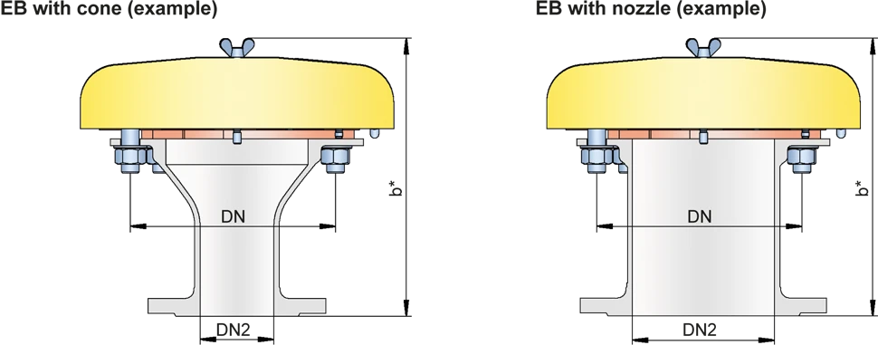
| EB-IIA and IIB with cone / nozzle** | |||||||||
| DN | 50 / 2" | 80 / 3" | 100 / 4" | 150 / 6" | |||||
| DN2 | ≤50 / 2“ | ≤80 / 3“ | ≤100 / 4 | ≤150 / 6“ | |||||
| b* | 238 / 9.37 | 263 / 10.35 | 383 / 15.08 | 313 / 12.32 | |||||
| Dimensions DN 200 - 800 / 8“ - 32“ for EB-IIA | |||||||||
| DN | 200 / 8" | 300 / 12" | 400 / 16" | 500 / 20" | 600 / 24" | 800 / 32“ | |||
| a | 405 / 15.94 | 555 / 21.85 | 705 / 27.75 | 855 / 33.66 | 1005 / 39.57 | 1210 / 47.64 | |||
| b | 177 / 6.97 | 206 / 8.11 | 235 / 9.25 | 265 / 10.43 | 294 / 11.57 | 330 / 12.99 | |||
| c | 496 / 19.53 | 650 / 25.59 | 802 / 31.57 | 987 / 38.86 | 1137 / 44.76 | 1336 / 52.60 | |||
| d | 900 / 35.43 | 1200 / 47.24 | 1500 / 59.06 | 1820 / 71.65 | 2120 / 83.46 | 2525 / 99.41 | |||
| f | 450 / 17.72 | 600 / 23.62 | 750 / 29.53 | 920 / 36.22 | 1070 / 42.13 | 1270 / 50.00 | |||
| g | 51 / 2.01 | 80 / 3.15 | 109 / 4.29 | 138 / 5.43 | 167 / 6.57 | 204 / 8.03 | |||
| EB-IIA with cone / nozzle** | |||||||||
| DN | 200 / 8" | 300 / 12" | 400 / 16" | 500 / 20" | 600 / 24" | 800 / 32" | |||
| DN2 | ≤200 / 8“ | ≤300 / 12“ | ≤400 / 16“ | ≤500 / 20“ | ≤600 / 24“ | ≤800 / 32“ | |||
| b* | 401 / 15.94 | 456 / 17.95 | 535 / 21.06 | 614 / 24.17 | 693 / 27.28 | 830 / 32.68 |
Dimensiones en mm / pulgadas
** combinations (DN/DN2) please use the table on the following page
Combination (DN/DN2) for EB with cone
Flow capacity charts for EB-DN/DN2-IIA/IIB with cone upon request
| DN | 50 / 2“ | 80 / 3“ | 100 / 4“ | 150 / 6“ | 200 / 8“ | 300 / 12“ | 400 / 16“ | 500 / 20“ | 600 / 24“ | 800 / 32“ |
| DN2 | ||||||||||
| 20 / ¾“ | IIA / IIB | IIA / IIB | IIA / IIB | IIA / IIB | ||||||
| 25 / 1“ | IIA / IIB | IIA / IIB | IIA / IIB | IIA / IIB | ||||||
| 32 / 1¼" | IIA / IIB | IIA / IIB | IIA / IIB | IIA / IIB | ||||||
| 40 / 1½" | IIA / IIB | IIA / IIB | IIA / IIB | IIA / IIB | ||||||
| 50 / 2“ | IIA / IIB | IIA / IIB | IIA / IIB | IIA / IIB | IIA | |||||
| 65 / 2½“ | IIA / IIB | IIA / IIB | IIA / IIB | |||||||
| 80 / 3“ | IIA / IIB | IIA / IIB | IIA / IIB | IIA | IIA | |||||
| 100 / 4“ | IIA / IIB | IIA / IIB | IIA | IIA | ||||||
| 125 / 5“ | IIA / IIB | IIA | ||||||||
| 150 / 6“ | IIA / IIB | IIA | IIA | IIA | ||||||
| 200 / 8“ | IIA | IIA | IIA | IIA | IIA | |||||
| 250 / 10“ | IIA | IIA | IIA | |||||||
| 300 / 12“ | IIA | IIA | IIA | |||||||
| 350 / 14“ | IIA | IIA | ||||||||
| 400 / 16“ | IIA | IIA | IIA | |||||||
| 450 / 18“ | IIA | IIA | IIA | |||||||
| 500 / 20“ | IIA | IIA | ||||||||
| 600 / 24“ | IIA | |||||||||
| 700 / 28“ | IIA |
Selección del grupo de explosión
| MESG | Expl. Gr. (IEC / CEN) | Gas Group (NEC) |
| > 0,90 mm | IIA | D |
| ≥ 0,50 mm | IIB | B |
Special approvals upon request
Selección de materiales para la vivienda
| Design | A | B |
| flange ring | Steel | Stainless Steel |
| Weather hood | Steel | Stainless Steel |
| cone / nozzle | Steel | Stainless Steel |
| Flame arrester unit Flame arrester unit Flame arrester casing with FLAMEFILTER® set. | A, B, C | B, C |
Special materials upon request
Combinación de materiales para la unidad apagallamas
| Design | A | B | C |
| FLAMEFILTER® cage | Steel | Stainless Steel | Stainless Steel / Hastelloy |
| FLAMEFILTER® | Stainless Steel | Stainless Steel | Hatselloy |
| Spider ring | Steel | Stainless Steel | Stainless Steel / Hastelloy |
Special materials upon request
Tipo de bridas de conexión
| EN 1092-1 (without cone); EN 1092-1; Form B1 (with cone / nozzle) |
| ASME B16.5 (without cone); ASME B16.5 CL 150 R.F. (with cone / nozzle) |
other types upon request
Diagrama de flujo volumétrico
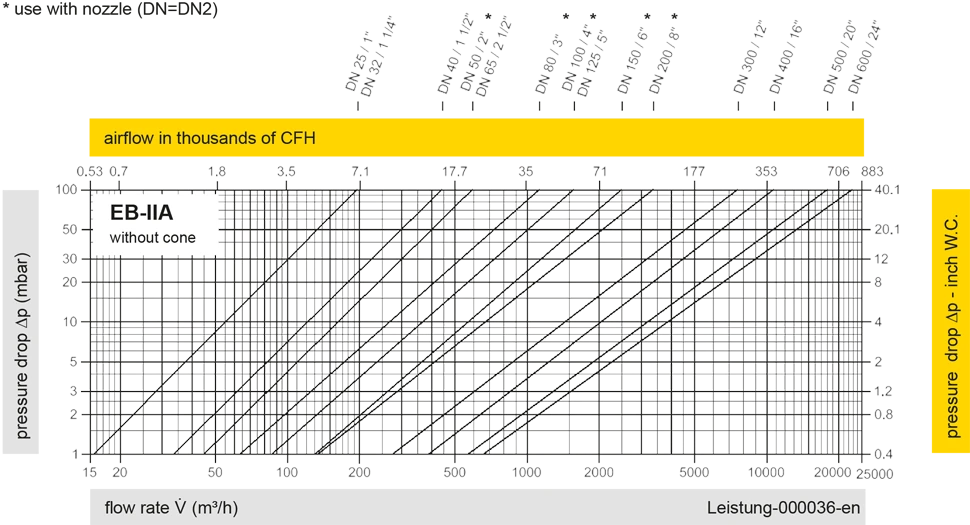
Remark: Flow capacity charts for EB-DN/DN2-IIA/IIB with cone upon request
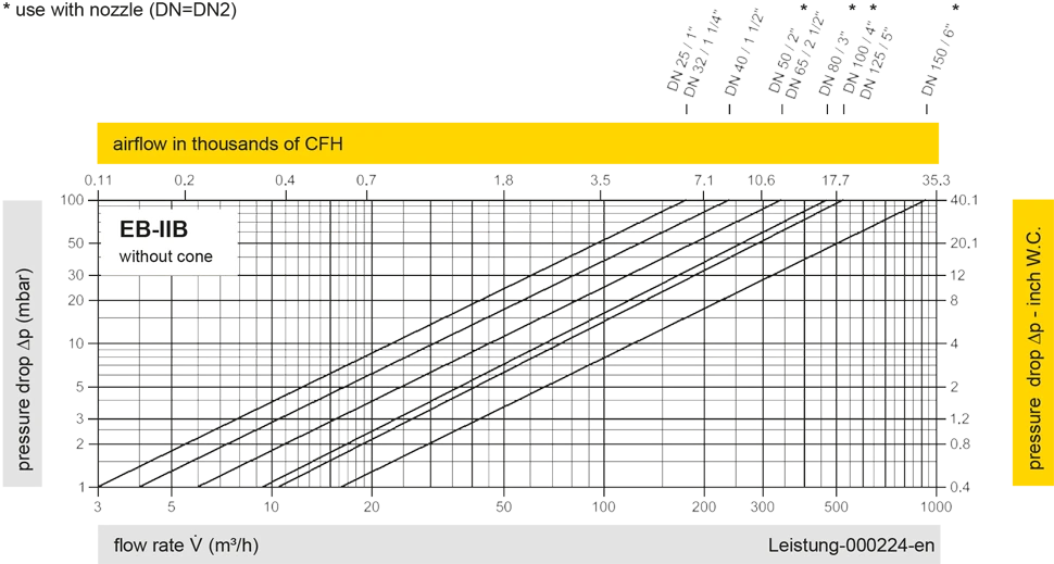
Los diagramas de flujo volumétrico han sido determinados con un banco de pruebas de caudal calibrado y certifi - cado por TÜV. El flujo volumétrico V. en [m³/h] y el CFH se refi eren a las condiciones estándar de referencia de aire según ISO 6358 (20°C, 1bar). La conversión a otras densidades y temperaturas están referidas en el Vol. 1: “Fundamentos Técnicos”.


Si tienes alguna pregunta, comentario o sugerencia, nuestro equipo de expertos estará encantado de ayudarte.
