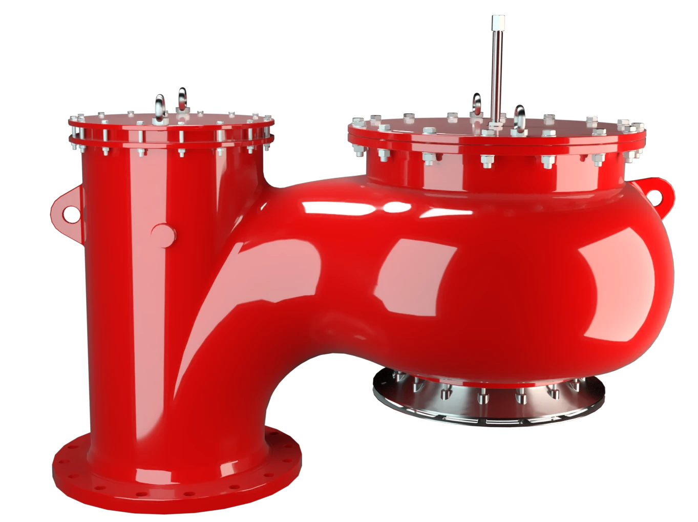
Features
10% Technology
Extreme Tightness
Optimal Pressure Maintenance
Flow Capacity
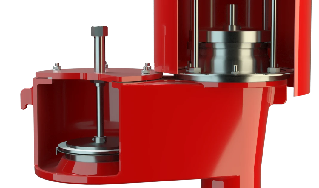
Guided Valve Pallet
Used in Explosion Hazardous Areas
Condensate Drainage
Highly Developed Vacuum Relief Valve

Full Lift Technology
Advanced Manufacturing Technology
Dimensiones
| DN | 400 / 16" |
| a | 690 / 27.17 |
| b | 470 / 18.50 |
| c | 750 / 29.53 |
| d | 435 / 17.13 |
| e | 1086 / 42.76 |
Dimensiones en mm / pulgadas
Dimensions for vacuum relief valve with heating jacket upon request
Selección de materiales para la vivienda
| Design | A | C | D |
| Housing Housing A housing is a solid shell, which surrounds a content, either protecting the content from external influences, or protecting the environment from the content. | Aluminium | Stainless Steel | Low Temperature Carbon Steel |
| Valve seat | Stainless Steel | Stainless Steel | Stainless Steel |
| Protective grating Protective grating Protective grating is used as a barrier against humans, animals, or debris, while still allowing flow of gases | Stainless Steel | Stainless Steel | Stainless Steel |
| Sealing | PTFE | PTFE | PTFE |
Option: Housing with ECTFE- lining Lining Protective plastic lining with a defined minimum/maximum thickness to protect against aggressive mixtures (e.g., acid).
Special materials upon request
Selección de materiales para la válvula de vacío
| Design | C | D | E | F |
| vacuum range [mbar] [inch W.C.] | -2.6 up to -4.4 -1.04 up to -1.76 | -4.4 up to -7.6 -1.76 up to 3.04 | -7.6 up to -13.2 -3.04 up to -5.28 | -13.2 up to -25 -5.28 up to -10 |
| Max.
Back pressure
Back pressure
The back pressure is the sum of built-up back pressure and superimposed back pressure.
[mbar] [inch W.C.] | 245 98 | 1690 676 | 580 232 | 2000 800 |
| Valve pallet Valve pallet Valve pallet is the generic term for the assembly that rests on the valve seat. | Aluminium, thin | Aluminium, thick | Stainless Steel, thin | Stainless Steel, thick |
| Sealing | Metal to Metal | Metal to Metal | Metal to Metal | Metal to Metal |
Special materials and higher vacuum settings upon request
Tipo de bridas de conexión
| EN 1092-1; Form B1 |
| ASME B16.5 CL 150 R.F. |
other types upon request
Diagrama de flujo volumétrico
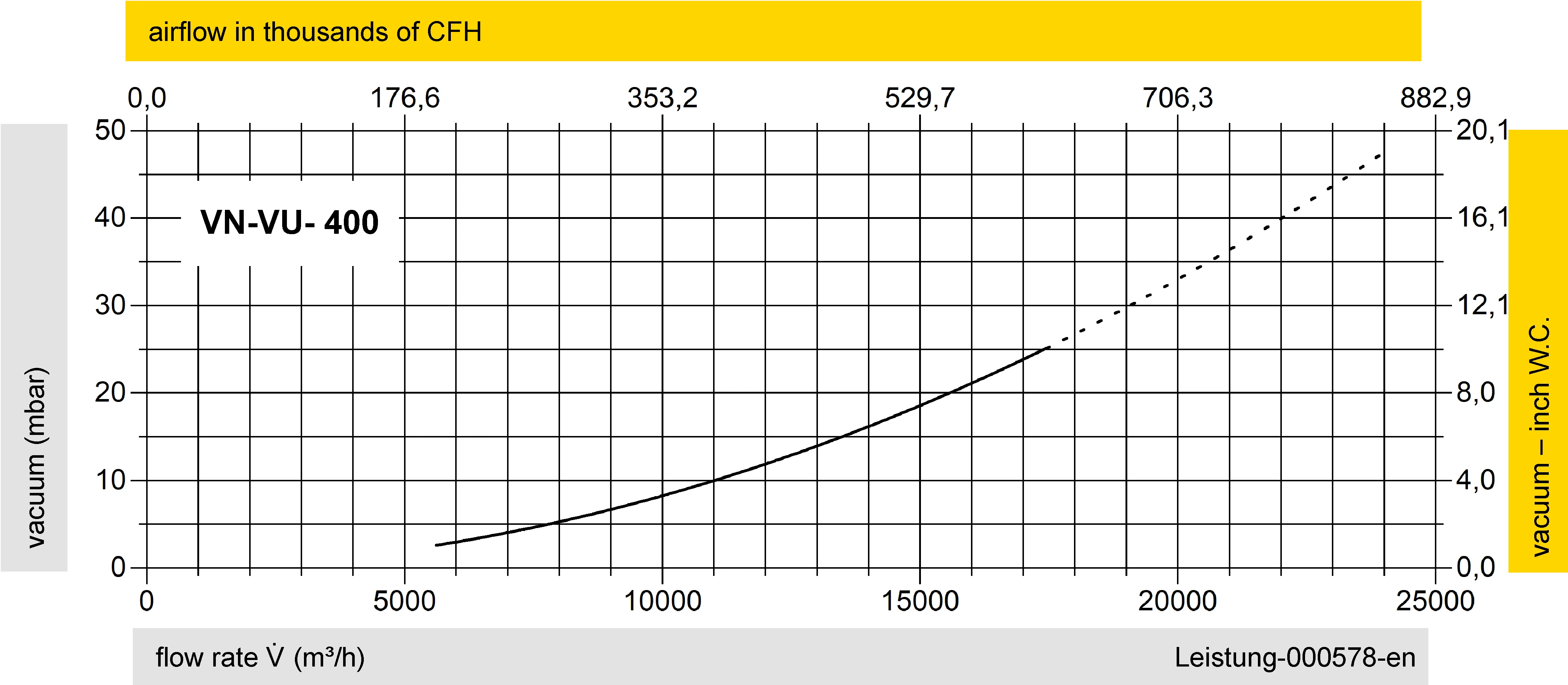
Los diagramas de flujo volumétrico han sido determinados con un banco de pruebas de caudal calibrado y certifi - cado por TÜV. El flujo volumétrico V. en [m³/h] y el CFH se refi eren a las condiciones estándar de referencia de aire según ISO 6358 (20°C, 1bar). La conversión a otras densidades y temperaturas están referidas en el Vol. 1: “Fundamentos Técnicos”.

Detail X


Si tienes alguna pregunta, comentario o sugerencia, nuestro equipo de expertos estará encantado de ayudarte.
