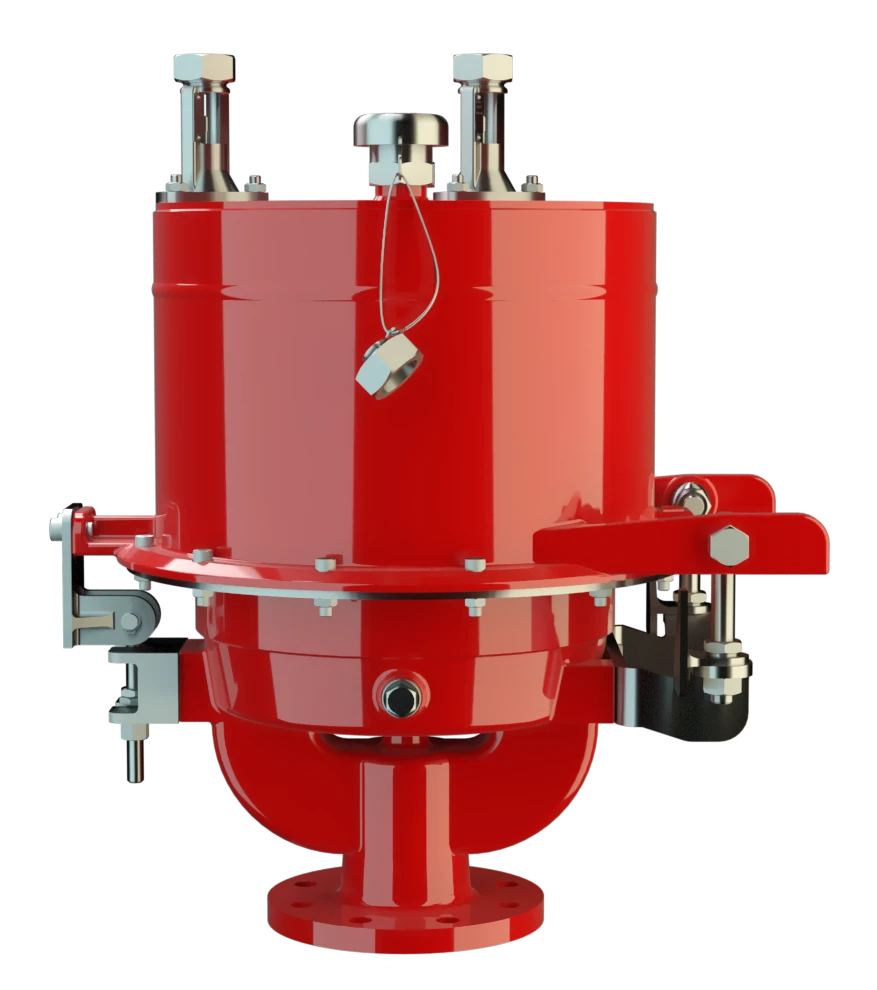
UB/SF-IIA1
Pressure/Vacuum Diaphragm Valve with internal coating, deflagration- and endurance burning-proof
Features
Extreme Tightness
Optimal Pressure Maintenance
Protective System According to ATEX
Digital Level Monitoring
Digital Level Sensors
Frost-Proof
Condensate Drainage
Monitoring
Modular Design
Easy Operation Monitoring
Safety Against Endurance Burning
Safe Venting
Combined Pressure and Vacuum Relief Valve
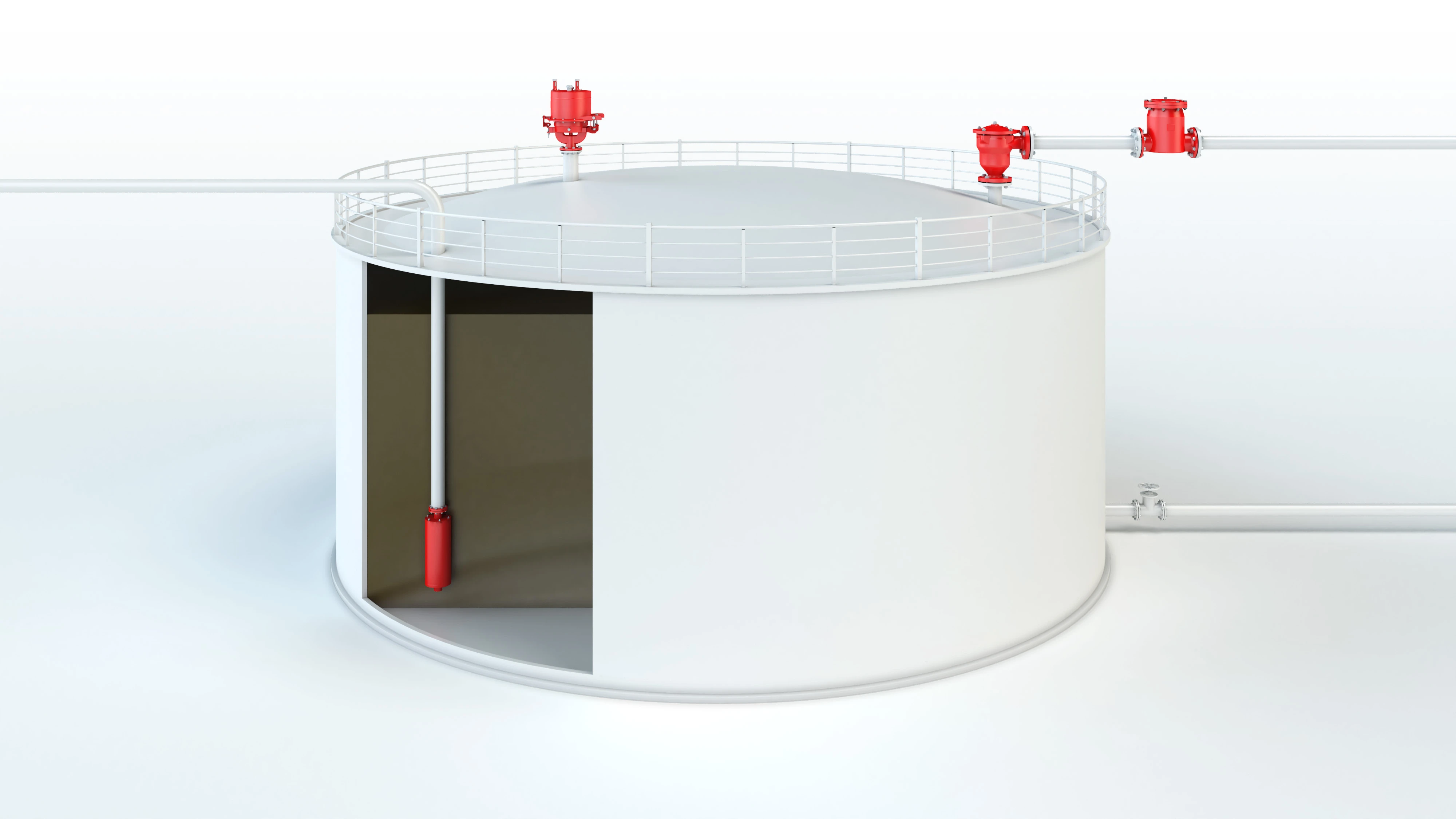
Usable Under Extreme Climatic Conditions
Composition
Advanced Sealing Technology for Reliable Pressure Maintenance in Tanks
Dynamic Flame Arresting Safety at Overpressure Conditions
Many Individual Certifications
Dimensiones
To select the nominal size Nominal size The nominal size is an alphanumeric designation of size for components in a piping system, used for reference purposes, comprising the letters DN followed by a dimensionless integer that is indirectly related to the physical size of the bore or outside diameter of the connections, expessed in millimeters. (DN), please use the flow capacity charts on the following pages
| DN | pressure | pressure | 80 / 3" | pressure | pressure | 100 / 4" | pressure | pressure | 150 / 6" |
| a | up to +28 mbar | up to +11.2 inch W.C. | 615 / 24.21 | up to +28 mbar | up to +11.2 inch W.C. | 645 / 25.39 | up to +25 mbar | up to +10 inch W.C. | 680 / 26.77 |
| a | > +28 mbar | > +11.2 inch W.C. | 765 / 30.12 | > +28 mbar | > +11.2 inch W.C. | 795 / 31.30 | > +25 mbar | > +10 inch W.C. | 830 / 32.68 |
| b | 410 / 16.14 | 485 / 19.09 | 590 / 23.23 |
Dimensiones en mm / pulgadas
Pressure settings > +50 mbar / +20 inch W.C. (DN 80), > +45 mbar / +18 inch W.C. (DN 100), > +46 mbar / +18.4 inch W.C. (DN150) with additional liquid reservoir - dimensions upon request
Dimensions for pressure/vacuum diaphragm valves with
heating coil
Heating coil
A heating coil is a pipe connection consisting of several pipe sections.
upon request
Selección del grupo de explosión
| MESG | Expl. Gr. (IEC / CEN) |
| ≥ 1,14 mm | IIA1 |
Special approvals upon request
Material for housing
| Design | B |
| Housing Housing A housing is a solid shell, which surrounds a content, either protecting the content from external influences, or protecting the environment from the content. | Steel |
| Coating Coating Coating is the application of a firmly adhering layer of shapeless material to the surface of a workpiece. of housing | 2 components polymere coating |
| Valve top | Stainless Steel |
| Heating coil (UB / SF-H-...-I) | Stainless Steel |
| Valve seats | Stainless Steel |
| Gasket | FPM |
| Diaphragm | FPM |
Special materials upon request
Tipo de bridas de conexión
| EN 1092-1; Form B1 |
| ASME B16.5 CL 150 R.F. |
other types upon request
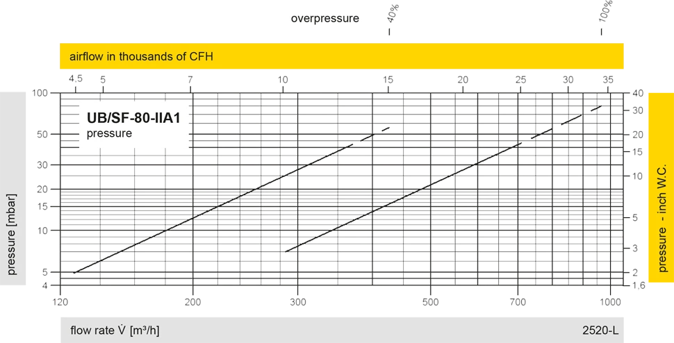
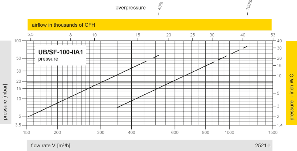
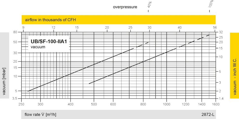
Diagrama de flujo volumétrico

UB/SF DN100
UB/SF DN150
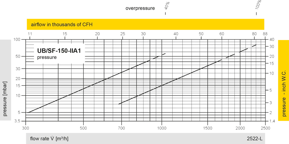
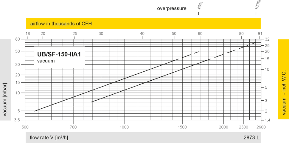
Los diagramas de flujo volumétrico han sido determinados con un banco de pruebas de caudal calibrado y certifi - cado por TÜV. El flujo volumétrico V. en [m³/h] y el CFH se refi eren a las condiciones estándar de referencia de aire según ISO 6358 (20°C, 1bar). La conversión a otras densidades y temperaturas están referidas en el Vol. 1: “Fundamentos Técnicos”.


Si tienes alguna pregunta, comentario o sugerencia, nuestro equipo de expertos estará encantado de ayudarte.
