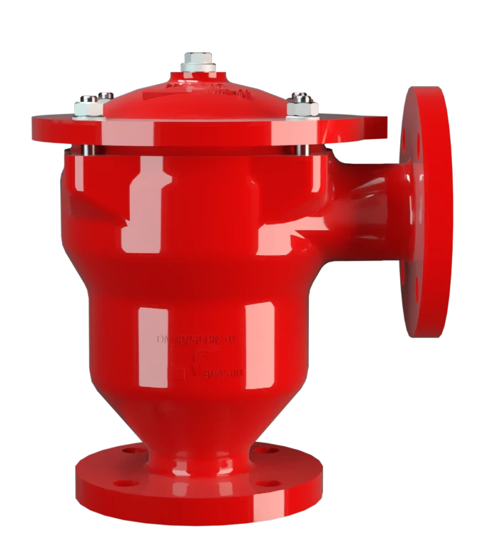
DR-UN
Apagallamas en línea a prueba de detonaciones estables y deflagraciones con ángulo de 90º y reductor de choque, unidireccional
Features
Montaje y desmontaje más rápido
Diseño modular
Piezas de recambio
Uso del efecto patentado del tubo guía de ondas de choque (SWGTE)
Bajo coste
Fácil mantenimiento
Aseguran instalaciones potencialmente explosivas frente a deflagraciones en tuberías y detonaciones estables

Para los grupos de explosión IIA a IIB3
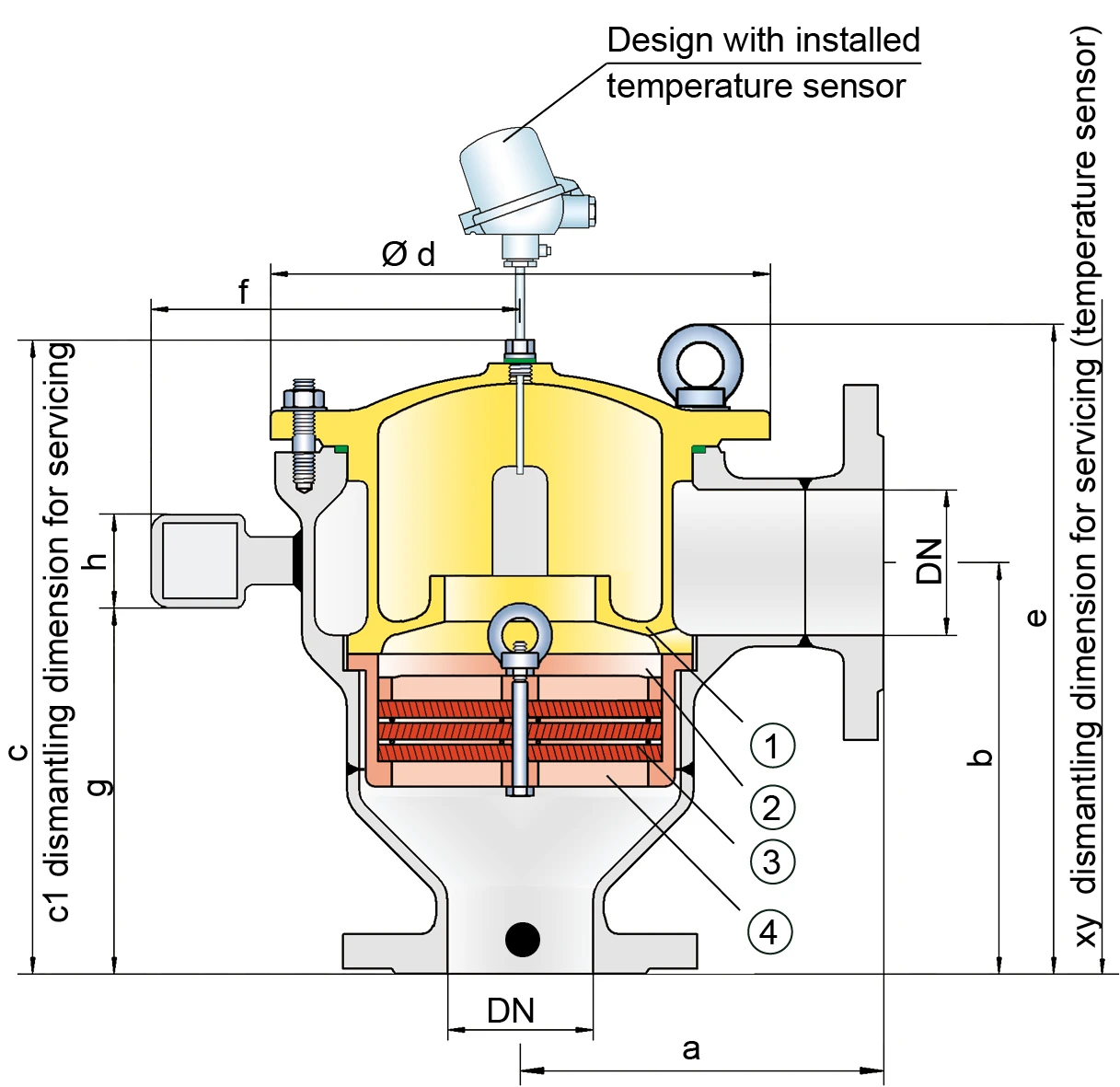
Dimensiones
Para seleccionar el tamaño nominal (DN), rogamos usar los diagramas de flujo volumétrico de las páginas siguientes
| DN | 25/ 1" | 32 / 1 ¼" | 40 / 1 ½" | 50 / 2" | 65 / 2 ½" | 80 / 3" | 100 / 4" | 150 / 6" | 200 / 8“ |
| a | 100 / 3.94 | 125 / 4.92 | 140 / 5.51 | 150 / 5.91 | 160 / 6.30 | 185 / 7.28 | 250 / 9.84 | 300 / 11.81 | 350 / 13.78 |
| b | 125 / 4.92 | 150 / 5.91 | 160 / 6.30 | 165 / 6.49 | 185 / 7.28 | 195 / 7.68 | 250 / 9.84 | 300 / 11.81 | 350 / 13.78 |
| c | 189 / 7.44 | 214 / 8.43 | 259 / 10.2 | 264 / 10.39 | 307 / 12.09 | 317 / 12.08 | 374 / 14.72 | 464 / 18.27 | 707 / 27.83 |
| c1 | 280 / 11.02 | 310 / 12.20 | 370 / 14.57 | 375 / 14.76 | 485 / 19.09 | 495 / 19.49 | 585 / 23.03 | 705 / 27.75 | 1170 / 46.06 |
| d | 149 / 5.87 | 149 / 5.87 | 210 / 8.27 | 210 / 8.27 | 275 / 10.83 | 275 / 10.83 | 325 / 12.80 | 460 / 18.11 | 620 / 24.41 |
| e | - | - | - | - | 326 / 12.83 | 336 / 13.23 | 403 / 15.87 | 475 / 18.70 | 707 / 27.83 |
| f | - | - | 168 / 6.61 | 168 / 6.61 | - | - | - | - | - |
| g | - | - | 138 / 5.43 | 143 / 5.63 | - | - | - | - | - |
| h | - | - | 50 / 1.97 | 50 / 1.97 | - | - | - | - | - |
| xy | 475 / 18.70 | 500 / 19.69 | 570 / 22.44 | 580 / 22.83 | 690 / 27.17 | 700 / 27.56 | 770 / 30.31 | 905 / 35.63 | 1305 / 51.38 |
Dimensiones en mm / pulgadas
* upon request
Selección del grupo de explosión
| MESG | Gr. Expl. (IEC / CEN) | Grupo de gas (NEC) |
| > 0,90 mm | IIA | D |
| ≥ 0,65 mm | IIB3 | C |
Selección de la máxima presión de operación
| Expl. Gr. | DN | 25/ 1" | 32 / 1 ¼" | 40 / 1 ½" | 50 / 2" | 65 / 2½" | 80 / 3" | 100 / 4" | 150 / 6" | 200 / 8“ |
| IIA | Pmax | - | - | - | 2,0 / 29.0 | 2,0 / 29.0 | 2,0 / 29.0 | 2,0 / 29.0 | 1,2 / 17.4 | 1,6 / 23.2 |
| IIB3 | Pmax | 1,4 / 20.3 | 1,4 / 20.3 | 1,4 / 20.3 | 1,4 / 20.3 | 1, 2 / 17.4 | 1, 2 / 17.4 | 1,2 / 17.4 | 1,2 / 17.4 | 1,1 / 15.9 |
Pmax = máxima presión de operación permitida en bar / psi absoluto
Especificación de la máx. temperatura de operación
| ≤ 60°C / 140°F | Tmáx - Temperatura máxima de operación admisible en °C |
Selección de materiales para la vivienda
| Modelo | B | C |
| Cuerpo | Acero | Acero inox |
| Cubierta con reductor de choque | Acero | Acero inox |
| Junta tórica | FPM | PTFE |
| Unidad apagallamas | A | C, D |
Materiales especiales bajo demanda
Combinación de materiales para la unidad apagallamas
| Diseño | A | C | D | |
| FLAMEFILTER® jaula | Acero | Acero inox | Acero inox | |
| FLAMEFILTER®* | Acero inox | Acero inox | Hastelloy | |
| Espaciador | Acero inox | Acero inox | Hastelloy |
* Other FLAMEFILTER® materials upon request
Materiales especiales bajo demanda
Tipo de bridas de conexión
| EN 1092-1; Form B1 |
| ASME B16.5 CL 150 R.F. |
Otros tipos bajo petición
Diagrama de flujo volumétrico

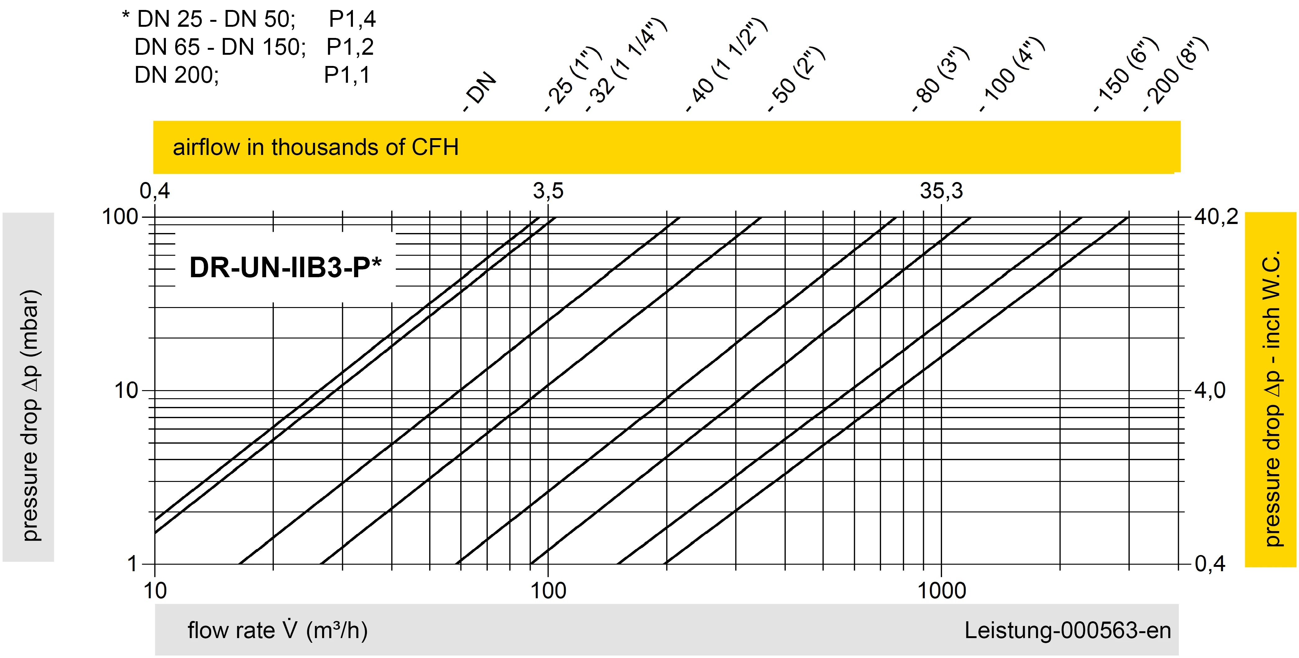
Los diagramas de flujo volumétrico han sido determinados con un banco de pruebas de caudal calibrado y certifi - cado por TÜV. El flujo volumétrico V. en [m³/h] y el CFH se refi eren a las condiciones estándar de referencia de aire según ISO 6358 (20°C, 1bar). La conversión a otras densidades y temperaturas están referidas en el Vol. 1: “Fundamentos Técnicos”.


Si tienes alguna pregunta, comentario o sugerencia, nuestro equipo de expertos estará encantado de ayudarte.
