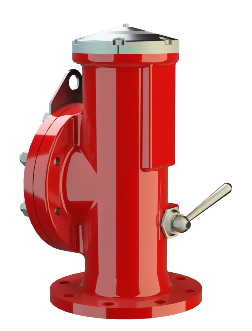
DE-S-IIC
High Velocity Pressure Relief Valve deflagration- and endurance burning-proof
Features
Pop-Open Characteristic
Extreme Tightness
Optimal Pressure Maintenance
Protective System According to ATEX
Safety Against Endurance Burning
Flow Capacity
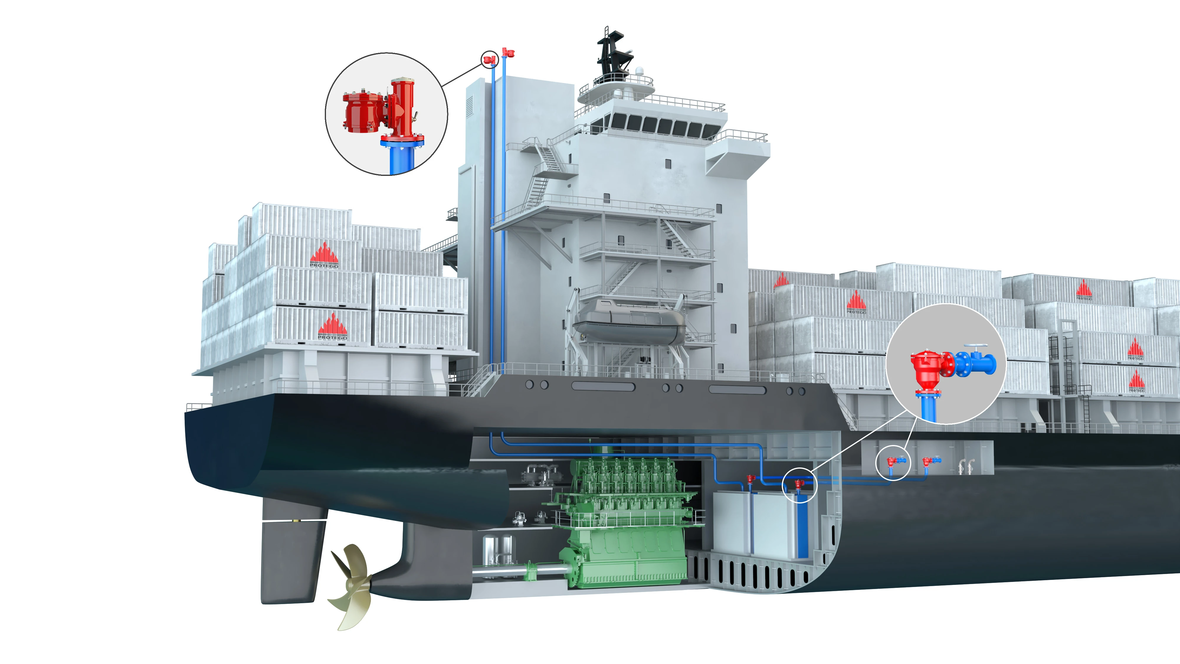
Suitable for Marine and Inland Tankers
Permanent Magnets
High-Speed Pressure Relief Valve
Jump Characteristic

Advanced Manufacturing Technology
Safety of the High-Speed Pressure Relief Valve
Prevention of Flame Flashback
Tested Against Oscillating Flow

Many Individual Certifications
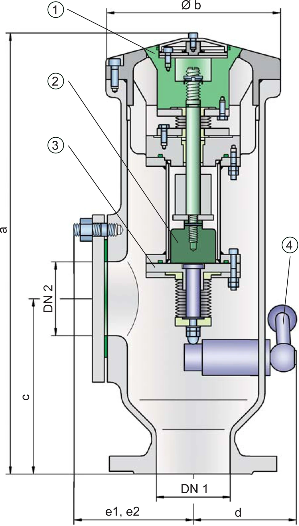
Dimensions
To select the nominal size Diamètre nominal The nominal size is an alphanumeric designation of size for components in a piping system, used for reference purposes, comprising the letters DN followed by a dimensionless integer that is indirectly related to the physical size of the bore or outside diameter of the connections, expessed in millimeters. (DN), please use the flow capacity chart on the following page
| DE-S-IIC with closed lateral connection DN 2 | ||||
| DN 1 | 80 / 3" | 100 / 4" | 150 / 6" | |
| a | 515 / 20.28 | 515 / 20.28 | 515 / 20.28 | |
| b | 195 / 7.68 | 195 / 7.68 | 195 / 7.68 | |
| c | 220 / 8.66 | 220 / 8.66 | 220 / 8.66 | |
| d | 120 / 4.72 | 120 / 4.72 | 120 / 4.72 | |
| e1 | 145 / 5.71 | 145 / 5.71 | 145 / 5.71 | |
| DE-S-IIC with lateral connection for vacuum relief valve Soupape de dépression A vacuum relief valve is used to ventilate a part of the system and protects it from impermissible underpressure. DN 2 | ||||
| DN 1 | 80 / 3" | 100 / 4" | 150 / 6" | 150 / 6" |
| DN 2 | 80 / 3" | 80 / 3" | 80 / 3" | 150 / 6" |
| a | 515 / 20.28 | 515 / 20.28 | 515 / 20.28 | 515 / 20.28 |
| b | 195 / 7.68 | 195 / 7.68 | 195 / 7.68 | 195 / 7.68 |
| c | 220 / 8.66 | 220 / 8.66 | 220 / 8.66 | 220 / 8.66 |
| d | 120 / 4.72 | 120 / 4.72 | 120 / 4.72 | 120 / 4.72 |
| e2 | 100 / 3.94 | 100 / 3.94 | 100 / 3.94 | 100 / 3.94 |
Dimensions in mm / inches
The maximum pipe length between the valve and the tank must be observed:
DN 80/3" and 100/4" = 5 m / 16.404 ft
DN 125/5" and 150/6" =7 m / 22.965 ft
Selection of explosion group
| MESG | Expl. Gr. (IEC / CEN) | Gas Group (NEC) |
| < 0,50 mm | IIC | B |
Special approvals upon request
Material selection
| Design | A | B | C |
| Housing | Steel | Stainless Steel | Hastelloy |
| Valve seat | Stainless Steel | Stainless Steel | Hastelloy |
| Valve cone | Stainless Steel | Stainless Steel | Hastelloy |
| Bellow | PTFE | PTFE | PTFE |
| Gasket | PTFE | PTFE | PTFE |
Special materials upon request
Flange connection type
| EN 1092-1; Form B1 |
| ASME B16.5 CL 150 R.F. |
other types upon request
Flow Capacity Chart
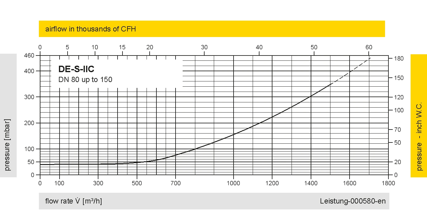
The flow capacity charts have been determined with a calibrated and TÜV certified flow capacity test rig. Volume flow V in (m³/h) and CFH refer to the standard reference conditions of air ISO 6358 (20°C, 1bar). For conversion to other densities and temperatures refer to Sec. 1: “Technical Fundamentals”.
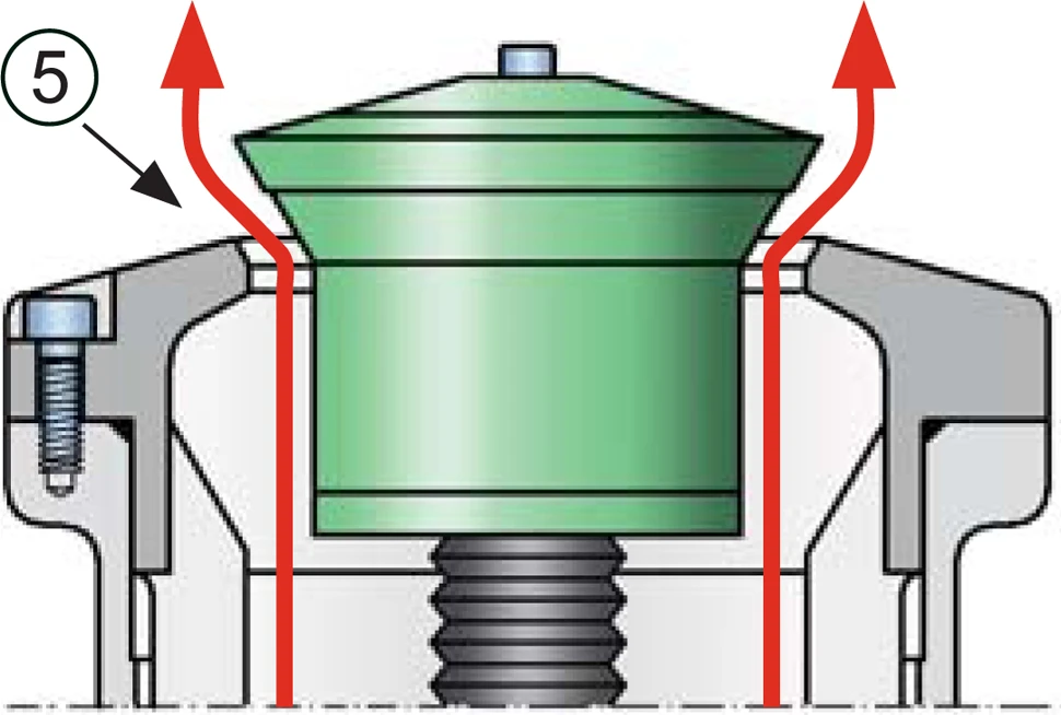
operating position of valve - open
Lateral connection DN2 for vacuum relief valve


Si vous avez des questions, des commentaires ou des suggestions, notre équipe d'experts se fera un plaisir de vous aider.
