FA-CN-IIA1
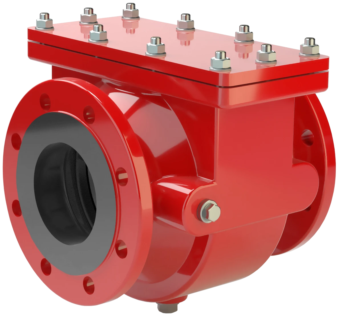
Apagallamas bidireccional en línea a prueba de deflagraciones para plantas de biogás, plantas de tratamiento de aguas residuales y vertederos. Diseño concéntrico.
Features
Extended Application Range
Compact Design
Spare Parts
Modular Design
Low Costs
Bi-Directional Flame Transmission
Dispositivo en línea compacto y de fácil mantenimiento, resistente a la combustión prolongada

Componente Principal: Apagallamas PROTEGO®
Para el grupo de explosión IIA1

Muchas certificaciones individuales
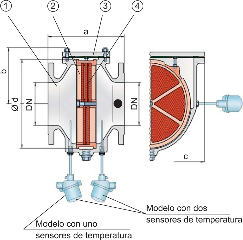
Dimensiones
Para seleccionar el tamaño nominal (DN), se ruega utilizar los diagramas de flujo volumétrico de las páginas siguientes
| DN | 40 / 1½" | 50 / 2" | 65 / 2½" | 80 / 3" | 100 / 4" | 125 / 5" | 150 / 6" | 200 / 8" | 250 / 10" | 300 / 12" |
| a | 210 | 215 | 235 | 240 | 265 | 305 | 310 | 300 | 320 | 350 |
| b | 105 | 105 | 132 | 132 | 150 | 197 | 197 | 220 | 260 | 295 |
| c | 200 | 200 | 260 | 260 | 308 | 415 | 415 | 446 | 520 | 600 |
| d | 130 | 130 | 185 | 185 | 220 | 310 | 310 | 355 | 420 | 490 |
Dimensiones en mm / pulgadas
Selección del grupo de explosión
| MESG | Gr. Expl. (IEC / CEN) |
| > 1.14 mm | IIA1 |
Homologaciones especiales bajo demanda
Selección de la máxima presión de operación
| DN | 40 / 1½" | 50 / 2" | 65 / 2½" | 80 / 3" | 100 / 4" | 125 / 5" | 150 / 6" | 200 / 8" | 250 / 10" | 300 / 12" |
| Pmax | 2.0 / 29.0 | 2.0 / 29.0 | 1,6 / 23.2 | 1,6 / 23.2 | 1,6 / 23.2 | 1,6 / 23.2 | 1,6 / 23.2 | 1,6 / 23.2 | 1,6 / 23.2 | 1,6 / 23.2 |
| Pmax | 2,5 / 36.3 | 2,5 / 36.3 | 2,5 / 36.3 | 2,5 / 36.3 | 2,5 / 36.3 | 2,5 / 36.3 | 2,5 / 36.3 | 2,5 / 36.3 | ||
| Pmax | 4,5 / 65.3 | 4,5 / 65.3 | 4,5 / 65.3 | 4,5 / 65.3 | 4,5 / 65.3 | 4,5 / 65.3 | 4,5 / 65.3 | |||
| Pmax | 5 / 72.5 | 5 / 72.5 |
Pmáx = máxima presión de operación en bar / psi absoluto, presiones de operación más altas bajo demanda
Especificación de la máx. temperatura de operación
| ≤ 60°C / 140°F | Tmáx - Temperatura máxima de operación admisible en °C |
| - | Designation |
Temperaturas de operación más altas bajo demanda
Tipo de bridas de conexión
| EN 1092-1; Form B1 |
| ASME B16.5 CL 150 R.F. |
Otros tipos bajo petición
Modelo y especificación
Existen tres tipos diferentes de diseño:Equipos adicionales especiales bajo demanda.
*Termómetro de resistencia para el equipo del grupo II, categoría (1) 2 (GII cat. (1) 2)
Selección de materiales
| Diseño | A | B | |
| Cuerpo | Acero | Acero inox | |
| Cubierta | Acero | Acero inox | |
| Junta | WS 3822* | PTFE | |
| Unidad apagallamas | Acero inox | Acero inox |
* para equipos expuestos a temperaturas de 150°C / 302°F (T150), juntas fabricadas con PTFE..
Materiales especiales bajo demanda
Diagrama de flujo volumétrico
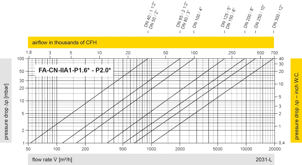
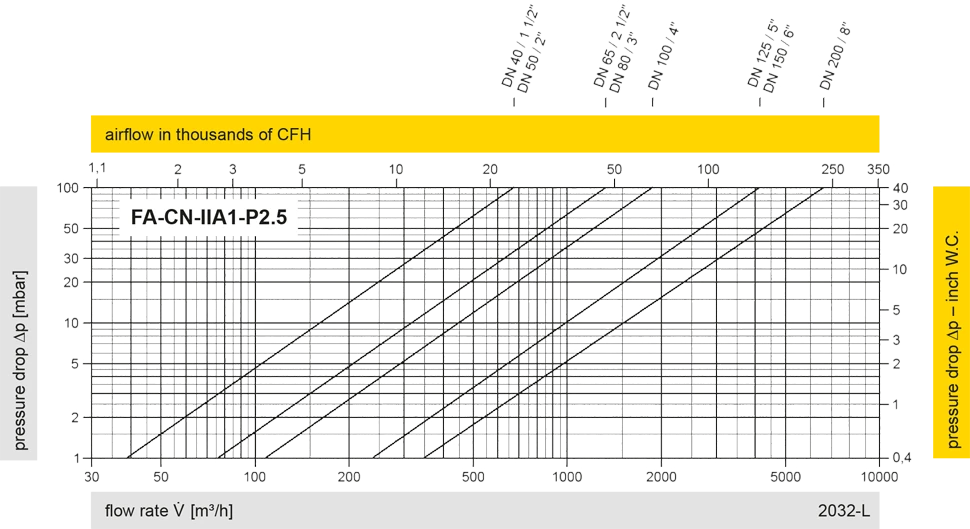
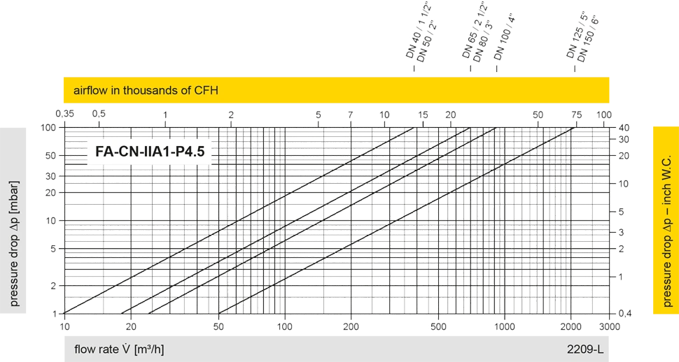
Los diagramas de flujo volumétrico han sido determinados con un banco de pruebas de caudal calibrado y certifi - cado por TÜV. El flujo volumétrico V. en [m³/h] y el CFH se refi eren a las condiciones estándar de referencia de aire según ISO 6358 (20°C, 1bar). La conversión a otras densidades y temperaturas están referidas en el Vol. 1: “Fundamentos Técnicos”.


Si tienes alguna pregunta, comentario o sugerencia, nuestro equipo de expertos estará encantado de ayudarte.
