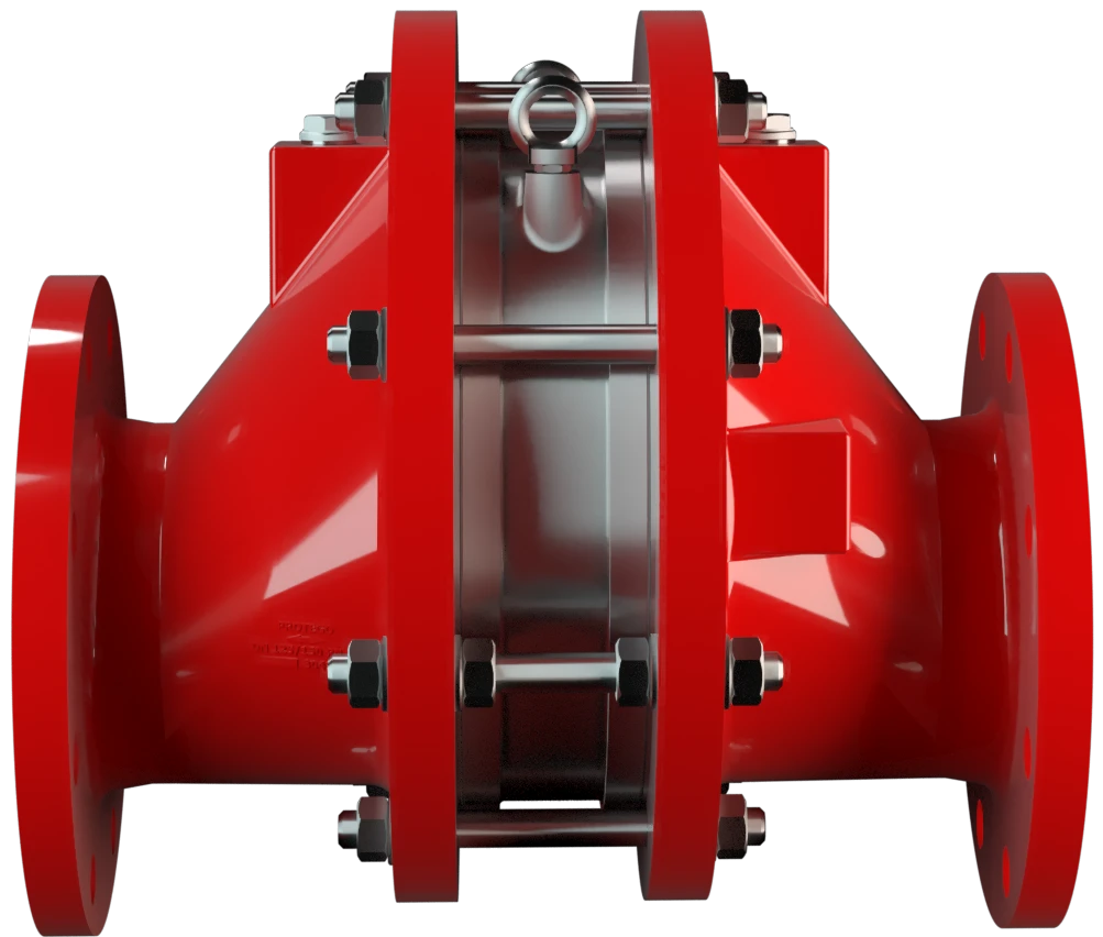
FA-E
Apagallamas en línea a prueba de deflagraciones diseño excéntrico, bidireccional
Features
Eccentric Design
Versatile Application Options
Bi-Directional Flame Transmission
Modular Design
Provides Safety
Spare Parts
Diseño excéntrico

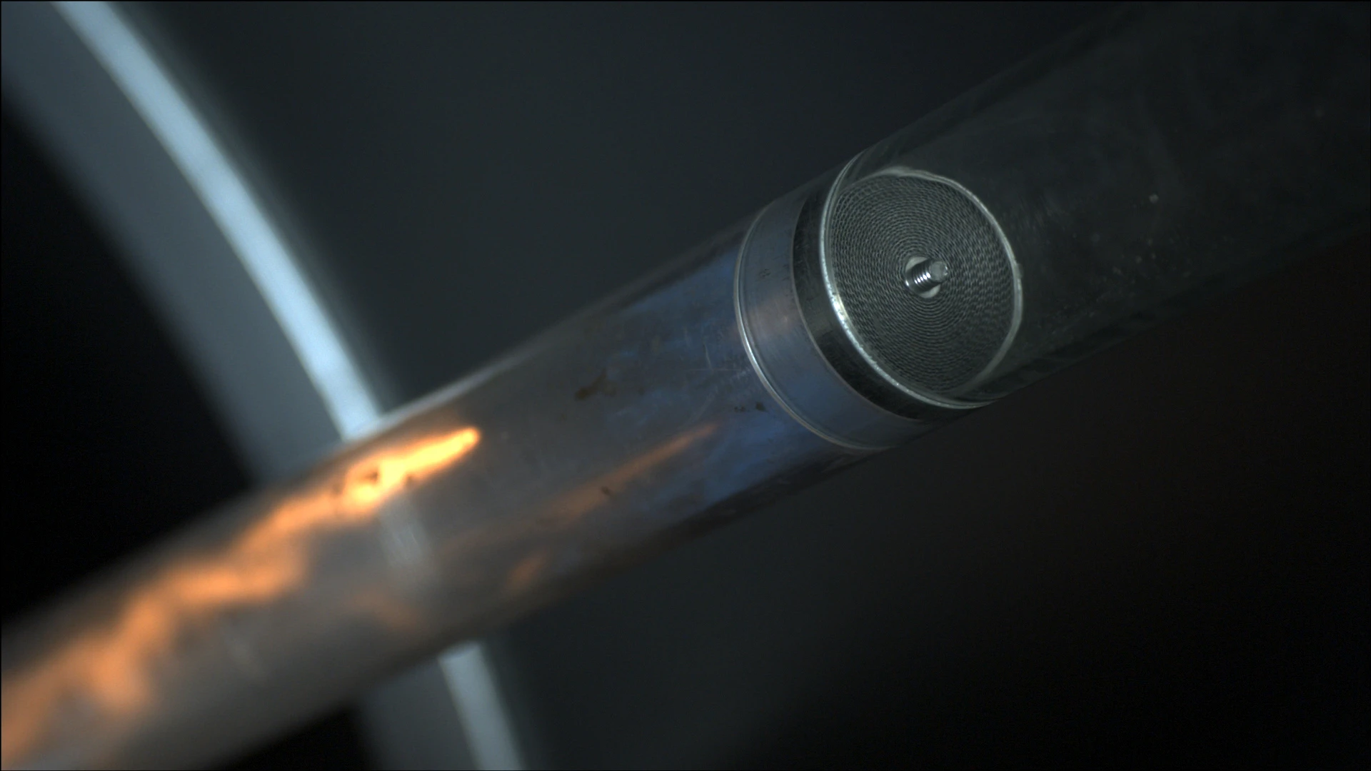
Componente Principal: Apagallamas PROTEGO®
Para los grupos de explosión IIA a IIC

Muchas certificaciones individuales
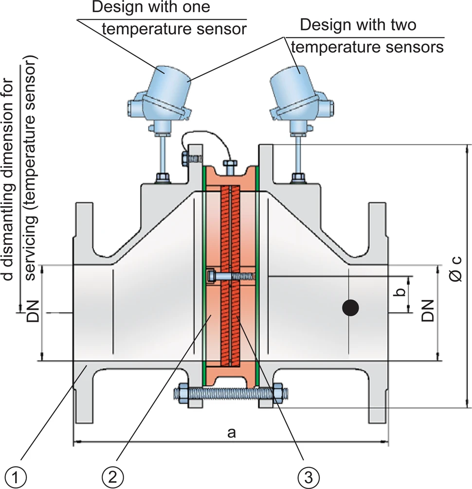
Dimensiones
Para seleccionar el tamaño nominal (DN), rogamos usar el diagrama de flujo volumétrico en las páginas siguientes
| Expl. Gr. | DN | 25 / 1" | 32 / 1¼“ | 40 / 1½“ | 50 / 2" | 65 / 2½“ | 80 / 3" | 100 / 4" | 125 / 5" | 150 / 6" | 200 / 8" | 250 / 10" | 300 / 12" |
| IIA | a | 304 / 11.97 | 304 / 11.97 | 310 / 12.20 | 314 / 12.36 | 360 / 14.17 | 364 / 14.33 | 370 / 14.57 | 434 / 17.09 | 440 / 17.32 | 450 / 17.72 | 480 / 18.90 | 500 / 19.69 |
| IIB3 | a | 304 / 11.97 | 304 / 11.97 | 310 / 12.20 | 314 / 12.36 | 360 / 14.17 | 364 / 14.33 | 370 / 14.57 | 434 / 17.09 | 440 / 17.32 | 450 / 17.72 | 480 / 18.90 | 500 / 19.69 |
| IIC | a | 304 / 11.97 | 304 / 11.97 | 321 / 12.64 | 325 / 12.80 | 371 / 14.61 | 375 / 10.83 | 381 / 15.00 | 445 / 17.52 | 451 / 17.76 | 461 / 18.15 | 491 / 19.33 | 511 / 20.12 |
| b | 29 / 1.14 | 29 / 1.14 | 29 / 1.14 | 29 / 1.14 | 38 / 1.49 | 38 / 1.49 | 39 / 1.53 | 65 / 2.56 | 65 / 2.56 | 55 / 2.17 | 58 / 2.28 | 60 / 2.36 | |
| c | 185 / 7.28 | 185 / 7.28 | 210 / 8.27 | 210 / 8.27 | 250 / 9.84 | 250 / 9.84 | 275 / 10.83 | 385 / 15.16 | 385 / 15.16 | 450 / 17.72 | 500 / 19.69 | 575 / 22.64 | |
| d | 400 / 15.75 | 400 / 15.75 | 410 / 16.14 | 410 / 16.14 | 440 / 17.32 | 440 / 17.32 | 460 / 18.11 | 520 / 20.47 | 520 / 20.47 | 540 / 21.26 | 570 / 22.44 | 600 / 23.62 |
Dimensiones en mm / pulgadas
Selección del grupo de explosión
| MESG | Gr. Expl. (IEC / CEN) | Grupo de gas (NEC) |
| > 0,90 mm | IIA | D |
| ≥ 0,65 mm | IIB3 | C |
| < 0,50 mm (> 0,50 mm) | IIC (IIB) | B |
Homologaciones especiales bajo demanda
Selección de la máxima presión de operación
| Expl. Gr. | DN | 25 / 1" | 32 / ¼" | 40 / 1½" | 50 / 2" | 65 / 2½" | 80 / 3" | 100 / 4" | 125 / 5" | 150 / 6" | 200 / 8" | 250 / 10" | 300 / 12" |
| IIA | Pmax | 1,6 / 23.2 | 1,6 / 23.2 | 1,6 / 23.2 | 1,6 / 23.2 | 1,6 / 23.2 | 1,6 / 23.2 | 1,6 / 23.2 | 1,6 / 23.2 | 1,6 / 23.2 | 1,6 / 23.2 | 1,6 / 23.2 | 1,6 / 23.3 |
| IIB3 | Pmax | 1,6 / 23.3 | 1,6 / 23.3 | 1,6 / 23.3 | 1,6 / 23.3 | 1,6 / 23.3 | 1,6 / 23.3 | 1,6 / 23.3 | 1,6 / 23.3 | 1,6 / 23.3 | 1,6 / 23.3 | 1,6 / 23.3 | 1,6 / 23.3 |
| IIC | Pmax | 1,1 / 15.9 | 1,1 / 15.9 | 1,1 / 15.9 | 1,1 / 15.9 | 1,1 / 15.9 | 1,1 / 15.9 | 1,2 / 15.9 | 1,1 / 15.9 | 1,1 / 15.9 | 1,1 / 15.9 | 1,1 / 15.9 | 1,1 / 15.9 |
Pmáx = Máxima presión de operación admisible en bar / psi absolutos, presiones de operación más altas bajo demanda
Especificación de la máx. temperatura de operación
| ≤ 60°C / 140°F | Tmáx - Temperatura máxima de operación admisible en °C |
| - | Designation |
Temperaturas de operación más altas bajo demanda
Tipo de bridas de conexión
| EN 1092-1; Form B1 |
| ASME B16.5 CL 150 R.F. |
Otros tipos bajo petición
Modelo y especificación
Existen tres diseños diferentes:Equipos especiales adicionales disponibles bajo demanda
*Termómetro de resistencia para el grupo de equipos II, categoría (1) 2 (GII cat. (1) 2)
Selección de materiales para la vivienda
| Diseño | B | C | D |
| Cuerpo | Acero | Acero inoxidable | Hastelloy |
| Junta | PTFE | PTFE | PTFE |
| Unidad apagallamas | A,C | C | D |
También se puede suministrar el cuerpo en acero al carbono con recubrimiento de ECTFE.
Materiales especiales bajo demanda.
Combinación de materiales para la unidad apagallamas
| Diseño | A | C | D |
| Jaula FLAMEFILTER® | Acero | Acero inoxidable | Hastelloy |
| Discos de llama FLAMEFILTER®* | Acero inoxidable | Acero inoxidable | Hastelloy |
| Espaciadores | Acero inoxidable | Acero inoxidable | Hastelloy |
* Los discos de filtro FLAMEFILTER® también están disponibles en los materials tántalo, inconel, cobre, etc. cuando se utilizan los materiales en el listado para el cuerpo y la jaula.
Materiales especiales bajo demanada.
Diagrama de flujo volumétrico
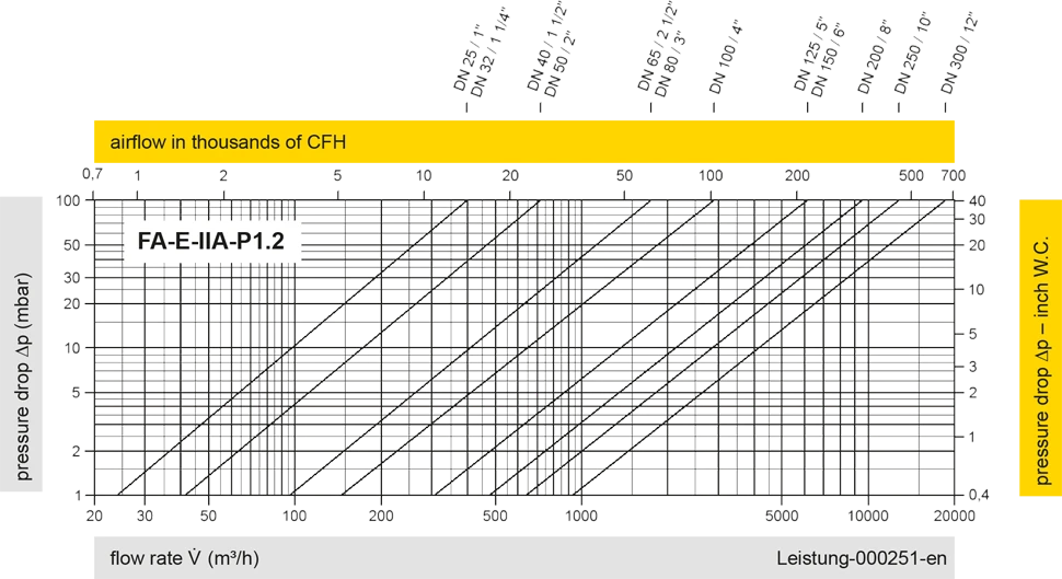
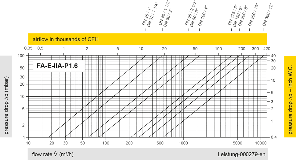
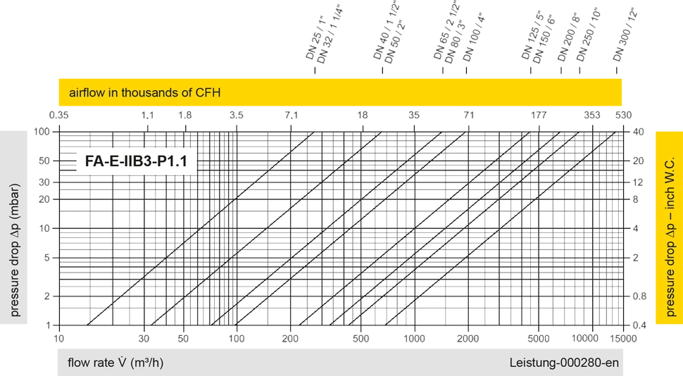
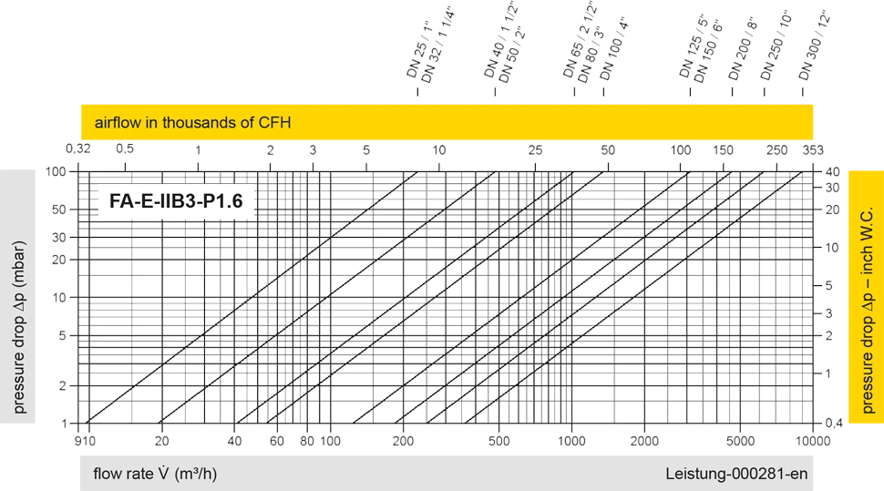
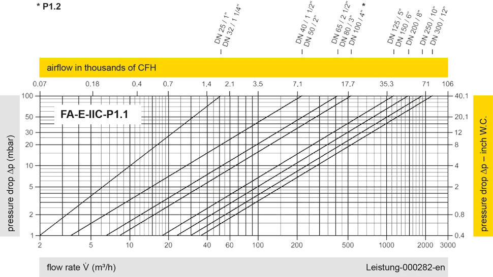
Los diagramas de flujo volumétrico han sido determinados con un banco de pruebas de caudal calibrado y certifi - cado por TÜV. El flujo volumétrico V. en [m³/h] y el CFH se refi eren a las condiciones estándar de referencia de aire según ISO 6358 (20°C, 1bar). La conversión a otras densidades y temperaturas están referidas en el Vol. 1: “Fundamentos Técnicos”.


Si tienes alguna pregunta, comentario o sugerencia, nuestro equipo de expertos estará encantado de ayudarte.
