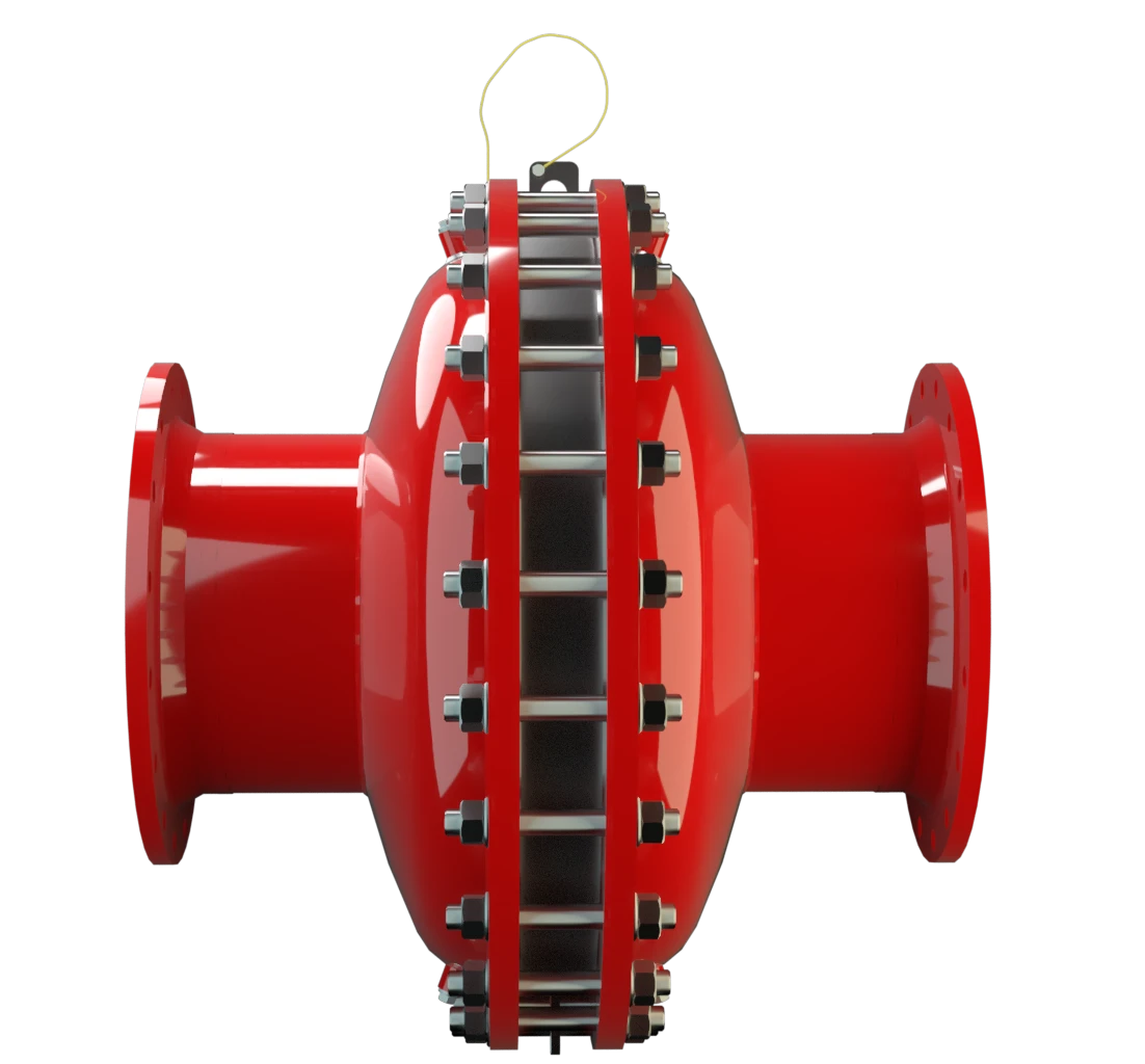
FA-I
Corta-chamas à prova de deflagração para tubulação construção concêntrica, de efeito bilateral
Features
Flow Capacity
Differnt Series
Low Costs
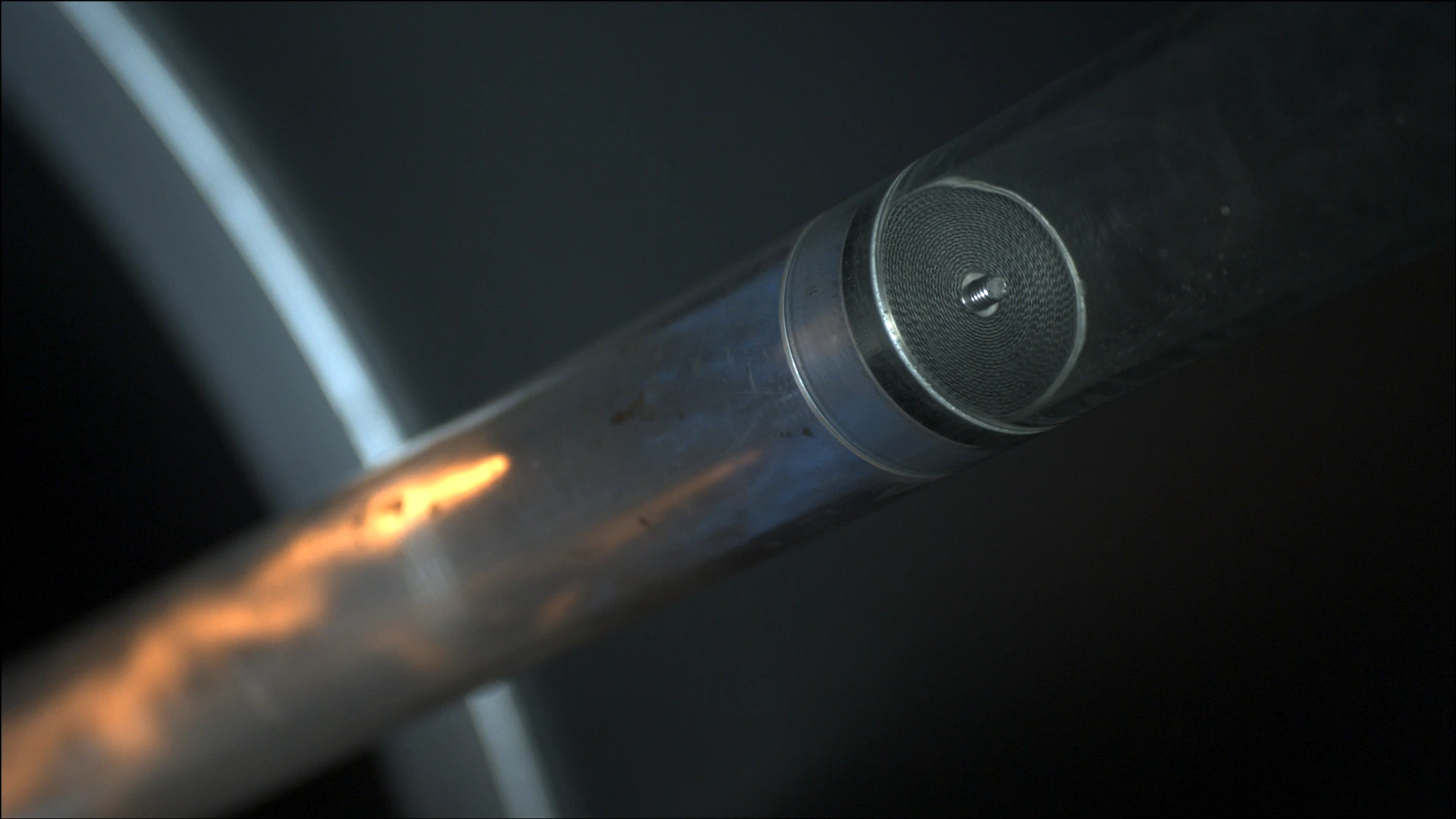
Integrated Cleaning Nozzles
Modular Design
Bi-Directional Flame Transmission
Provides Safety
Extended Application Range
Large Sizes
Spare Parts
Desempenho de fluxo eficiente

Componente Principal – Conjunto Abafador de Chamas PROTEGO®
Para o grupo de explosão IIA a IIB3

Muitas certificações individuais
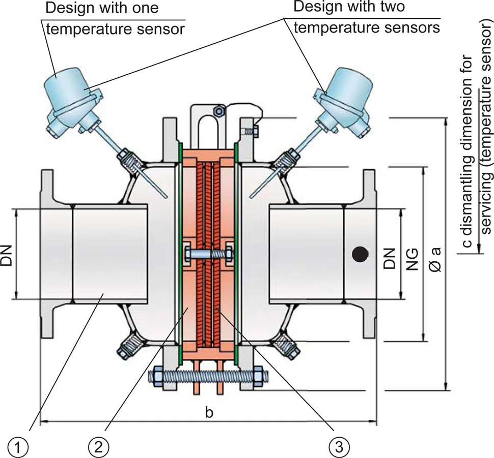
Tabela de dimensões
Para selecionar a série e a combinação entre diâmetros nominais (DN) e tamanhos nominais (NG), use os diagramas de vazão da páginas seguintes.
| Standard | ||||||||||||
| NG | 150 / 6“ | 150 / 6“ | 200 / 8“ | 300 / 12“ | 400 / 16“ | 500 / 20“ | 600 / 24“ | 800 / 32“ | 1000 / 40“ | 1200 / 48“ | 1400 / 56“ | 1600 / 64“ |
| DN | ≤50 / 2" | 80 / 3" | ≤100 / 4" | ≤150 / 6" | ≤200 / 8" | ≤250 / 10" | ≤300 / 12" | ≤400 / 16" | ≤500 / 20" | ≤600 / 24" | ≤800 / 32" | ≤800 / 32" |
| a | 285 | 285 | 340 | 445 | 565 | 670 | 780 | 975 | 1175 | 1405 | 1630 | 1830 |
| Expl. Gr. | ||||||||||||
| IIA b* | 364 | 364 | 452 | 584 | 638 | 688 | 800 | 900 | 1000 | 1100 | 1350 | 1450 |
| IIB3 b* | 364 | 364 | 464 | 596 | 650 | 700 | 800 | 900 | 1000 | 1100 | 1350 | 1450 |
| c | 500 | 500 | 520 | 570 | 620 | 670 | 800 | 900 | 1000 | 1100 | 1350 | 1450 |
Dimensões em mm
*A medida b somente se aplica a P1,2 (IIA) e P1,1 (IIB3).
Seleção do grupo de explosão
| MESG | Gr. expl. (IEC / CEN) | Grupo gás (NEC) |
| > 0,90 mm | IIA | D |
| ≥ 0,65 mm | IIB3 | C |
Aprovações especiais sob solicitação
Seleção da pressão máx. de trabalho
| Expl. Gr. | DN | 50 / 1" | 80 / 3" | 100 / 4" | 150 / 6" | 200 / 8" | 250 / 10" | 300 / 12" | 400 / 16" | 500 / 20" | 600 / 24" | 800 / 32" | 800 / 32" |
| NG | 150 / 6'' | 150 / 6'' | 200 / 8'' | 300 / 12'' | 400 / 16'' | 500 / 20'' | 600 / 24'' | 800 / 32'' | 1000 / 40'' | 1200 / 48'' | 1400 / 56" | 1600 / 64'' | |
| IIA | Pmax | 1,8 | 1,8 | 1,5 | 1,5 | 1,5 | 1,5 | 1,5 | 1,4 | 1,3 | 1,3 | 1,2 | 1,1 |
| IIB3 | Pmax | 1,2 | 1,2 | 1,2 | 1,2 | 1,2 | 1,2 | 1,2 | 1,2 | 1,2 | 1,1 | 1,1 | 1,1 |
Pmáx. = pressão de trabalho máxima admissível em bar absoluta, pressão de trabalho mais elevada sob solicitação
Proporção L/D máxima
| padrão | NG | 150 / 6" | 150 / 6" | 200 / 8'' | 300 / 12" | 400 / 16" | 500 / 20" | 600 / 24" | 800 / 32" | 1000 / 40'' | 1200 / 48'' | 1400 / 56'' | 1600 / 64'' |
| DN | ≤50 / 2" | 80 / 3" | ≤100 / 4" | ≤150 / 6" | ≤200 / 8" | ≤250 / 10" | ≤300 / 12" | ≤400 / 16" | ≤500 / 20" | ≤600 / 24" | ≤800 / 32" | ≤800 / 32" | |
| IIA | (L / D)máx | 50 | 50 | 50 | 50 | 50 | 50 | 50 | 50 | 50 | 50 | 50 | 50 |
| IIA | Pmáx | 1,2 | 1,2 | 1,2 | 1,2 | 1,2 | 1,2 | 1,2 | 1,2 | 1,3 | 1,3 | 1,2 | 1,1 |
| IIA | Identificação | - | - | - | - | - | - | - | - | - | - | - | |
| IIB3 | (L / D)máx | 50 | 50 | 40 | 40 | 35 | 35 | 35 | 30 | 30 | 30 | 25 | 25 |
| IIB3 | Pmáx | 1,1 | 1,1 | 1,1 | 1,1 | 1,1 | 1,1 | 1,1 | 1,1 | 1,1 | 1,1 | 1,1 | 1,1 |
| IIB3 | Identificação | - | - | X6 | X6 | X7 | X7 | X7 | X8 | X8 | X8 | X9 | X9 |
Indicação da temperatura máx. de trabalho
| ≤ 60°C / 140°F | Ttemperatura máxima de trabalho admissível em °C |
| - | Designation |
temperaturas de trabalho mais elevadas, sob solicitação
Seleção do material do corpo
| Execução | A | B | C |
| Corpo | aço | aço inoxidável | Hastelloy |
| Vedação | PTFE | PTFE | PTFE |
| Conjunto abafador de chamas | A, B | C | D |
O corpo também pode ser fornecido em aço, com revestimento em ECTFE. Materiais especiais sob solicitação
Combinações de material do conjunto abafador de chamas
| Execução | A | C | D |
| Armação do FLAMEFILTER® | aço | aço inoxidável | Hastelloy |
| FLAMEFILTER®* | aço inoxidável | aço inoxidável | Hastelloy |
| Espaçadores | aço inoxidável | aço inoxidável | Hastelloy |
* os FLAMEFILTER® também podem ser fornecidos em tântalo, Inconel, cobre, etc. em caso de utilização dos materiais do corpo ou da armação listados.
Materiais especiais sob solicitação.
Tipo de conexão flangeada
| EN 1092-1; Form B1 |
| ASME B16.5 CL 150 R.F. |
Outras conexões sob solicitação
Diagrama de vazão
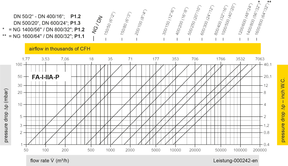
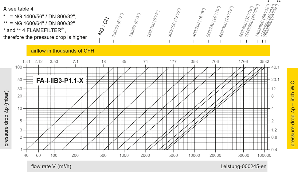
Este diagrama de vazão foi determinado em uma bancada de medição de vazão calibrada e certificada pela TÜV. A vazão V em m³/h se refere ao estado técnico padrão de ar, conforme ISO 6358 (20°C, 1bar). Para conversão em outras densidades e temperaturas, veja o cap. 1: Bases técnicas.


Se você tiver alguma dúvida, comentário ou sugestão, nossa equipe de especialistas terá prazer em ajudá-lo.
