Features
10% Technology
for Minimum Pressure Increase up to Full Lift
Extreme Tightness
Resulting in Lowest Possible Product Losses and Reduced Environmental Pollution
Optimal Pressure Maintenance
Set Pressure Close to Opening Pressure for Optimum Pressure Maintenance in the System
Guided Valve Pallet
Valve Pallet Is Guided Inside the Housing to Protect Against Harsh Weather Conditions
Non-Corrosive
Weight Reduction
in Comparison to Steel/Stainless Steel
Condensate Drainage
Automatic Condensate Drain
Aggressive, Sticky, or Polymerizing Products
Especially Suitable for Aggressive, Sticky, or Polymerizing Substances
Different Plastics
can Easily Be Combined
Function and Description
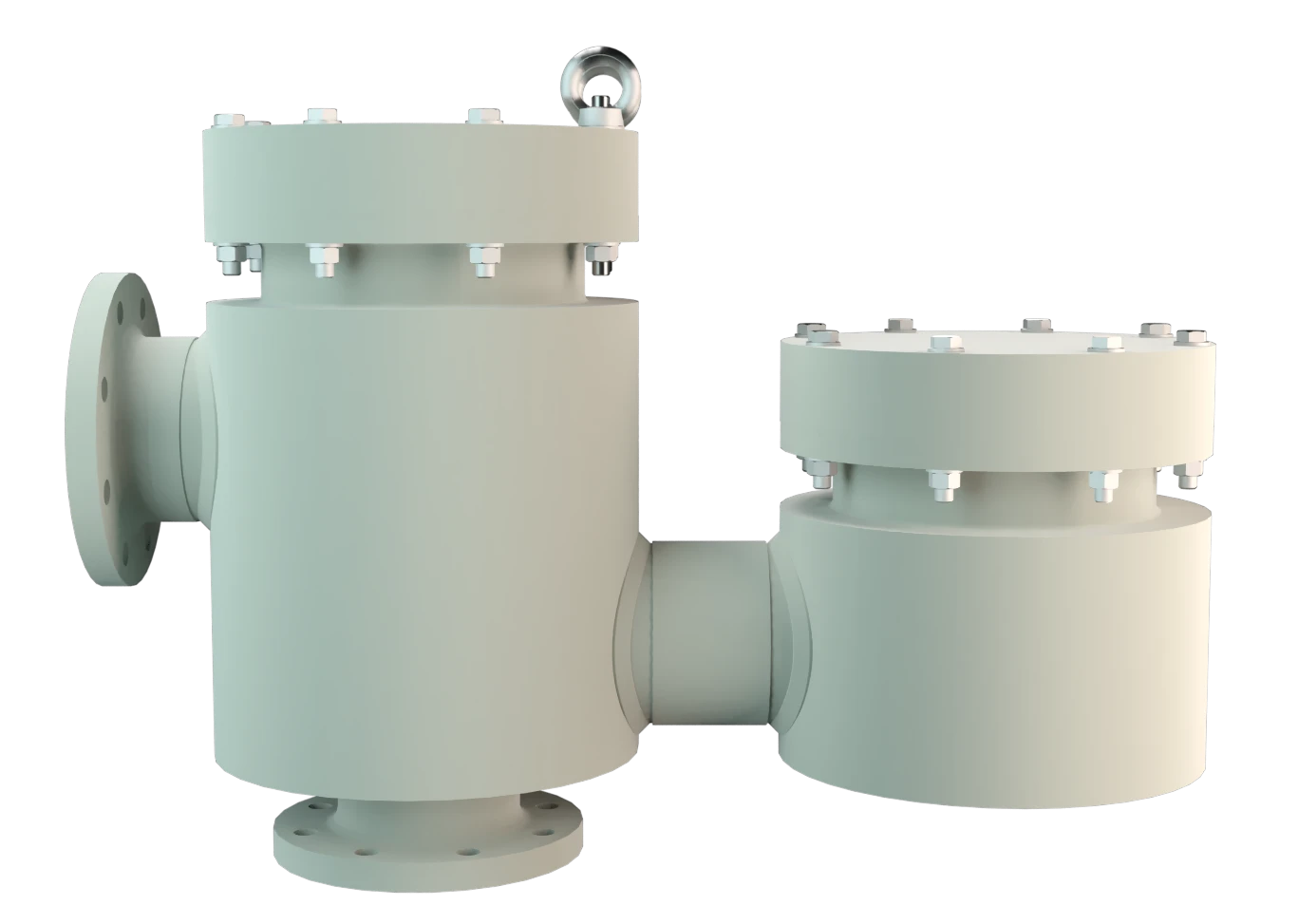
Válvula combinada de alívio de pressão e vácuo
A
Pressure/vacuum relief valve
Pressure/vacuum relief valve is an umbrella term that includes pressure or vacuum relief valve as well as pressure and vacuum relief valve.
válvula do tipo PROTEGO® VD/KSM -PA é uma válvula de alívio de pressão e vácuo em plástico. Ela é principalmente usada para o respiro de tanques, vasos e aparelhos de processos para protegê- los de pressão e vácuo inadmissíveis. Além disso, evitam-se emissões quase até atingir a pressão de ajuste e a entrada de produtos inadmissíveis é impedida. Os vapores de produtos são coletados por um sistema de tubulação conectado ao flange no lado de pressão. A válvula é especialmente adequada para o uso com produtos agressivos, pegajosos ou polimerizantes.

Tecnologia de curso pleno
Ao alcançar a pressão de ajuste a válvula inicia a abertura e atingen o curso pleno dentro de um aumento de pressão ou sobrepressão de 10%. Com investimentos específicos em pesquisa e desenvolvimento PROTEGO® pode adaptar o comportamento de abertura típico das válvulas de segurança convencionais à faixa de baixas pressões. Essa “Tecnologia de curso pleno“ permite definir a pressão de ajuste 10% abaixo da pressão admissível do tanque para garantir o fluxo necessário.
Tecnologia avançada de manufatura
Até alcançar a pressão de ajuste, garante-se a conservação da pressão do tanque com uma estanqueidade muito acima do padrão normal graças a tecnologia de fabricação altamente desenvolvida. Esta característica se obtém por exemplo, com sedes de válvulas em plástico de alta eficiência e vedações PTFE de ótima qualidade. Depois de aliviar o excesso de pressão e compensar o vácuo, a válvula fecha e proporciona uma vedação firme.
A otimização do corpo da válvula favoravel ao fluxo e a construção do obturador são resultado de anos de desenvolvimento, redundando em um funcionamento estável do obturador da válvula, ótima performance e redução da perda de produtos.
Product Data
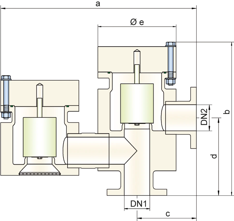
Tabela de dimensões
Para escolher o diâmetro nominal (DN), veja os diagramas de vazão nas páginas seguintes
| DN1 | 50 / 2" | 80 / 3" | 100 / 4" | 150 / 6" | 200 / 8" |
| DN2 | 50 / 2" | 80 / 3" | 100 / 4" | 150 / 6" | 200 / 8" |
| a | 490 | 650 | 775 (750)* | 930 (958)* | 1260 (1200)* |
| b | 376 | 521 | 563 (523)* | 670 (651)* | 879 (912)* |
| c | 150 | 200 | 225 | 280 | 350 |
| d | 200 | 245 | 300 | 370 | 590 (650)* |
| e | 180 | 250 | 300 | 350 (405)* | 560 (500)* |
Dimensões em mm
* Dimensões entre parênteses para aparelhos em PVDF
Seleção do material do corpo
| Execução | A | B | C |
| Corpo | PE | PP | PVDF |
| Sedes de válvulas | PE | PP | PVDF |
| Vedação | FPM | FPM | FPM |
| Obturador da válvula de alívio de pressão | A, C, D | B, C, D | C, D |
| Obturador da válvula de vácuo | A, C, D | B, C, D | C, D |
Materiais especiais sob solicitação
Seleção do material do disco da válvula de pressão
| Execução | A | B | C | D |
| Faixa de pressão [mbar] | +6,0 até +16 | +5,5 até +16 | +9,5 até +30 | +30 até +100 |
| Obturador da válvula | PE | PP | PVDF | Hastelloy |
| Vedação | PTFE | PTFE | PTFE | PTFE |
| Guia da haste | PE | PP | PVDF | Hastelloy |
| Peso | PE | PP | PVDF | Hastelloy |
Materiais especiais e ajustes de pressão mais altos ou baixos sob solicitação
Seleção do material do disco da válvula de vácuo
| Execução | A | B | C | D |
| Faixa de pressão [mbar] | -6,0 até -16 | -5,5 até -16 | -9,5 até -30 | -30 até -100 |
| Obturador da válvula | PE | PP | PVDF | Hastelloy |
| Vedação | PTFE | PTFE | PTFE | PTFE |
| Guia da haste | PE | PP | PVDF | Hastelloy |
| Peso | PE | PP | PVDF | Hastelloy |
Materiais especiais e ajustes de vácuo mais altos ou baixos sob solicitação
Tipo de conexão flangeada
| EN 1092-1; Form B1 |
| ASME B16.5 CL 150 F.F. |
Outras conexões sob solicitação
Diagrama de vazão
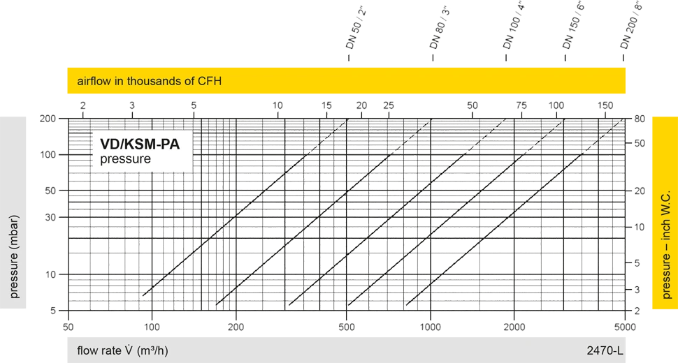
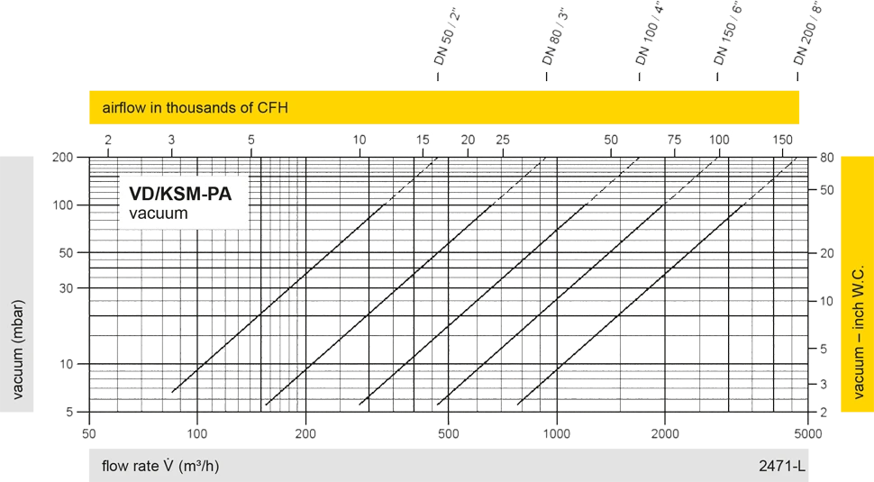
Este diagrama de vazão foi determinado em uma bancada de medição de vazão calibrada e certificada pela TÜV. A vazão V em m³/h se refere ao estado técnico padrão de ar, conforme ISO 6358 (20°C, 1bar). Para conversão em outras densidades e temperaturas, veja o cap. 1: Bases técnicas.


Se você tiver alguma dúvida, comentário ou sugestão, nossa equipe de especialistas terá prazer em ajudá-lo.
