LDA
Corta-chamas à prova de detonação por produto líquido para tubulações de enchimento – montagem interna
Features
Low Risk
Low Risk of Fouling
Meets TRGS Requirements
TRGS = Technical Regulations for Hazardous Substances
Different Connections
Available With Different Connections
Explosion Safety
Provides Protection Against Deflagration and Stable Detonation
For Flammable Liquids
Useable for Nearly All Flammable Liquids
Low Pressure Loss
Function and Description
Prevenção da propagação de chamas no tanque durante a ignição
O
Pressure/vacuum relief valve
Pressure/vacuum relief valve is an umbrella term that includes pressure or vacuum relief valve as well as pressure and vacuum relief valve.
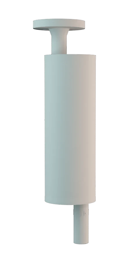
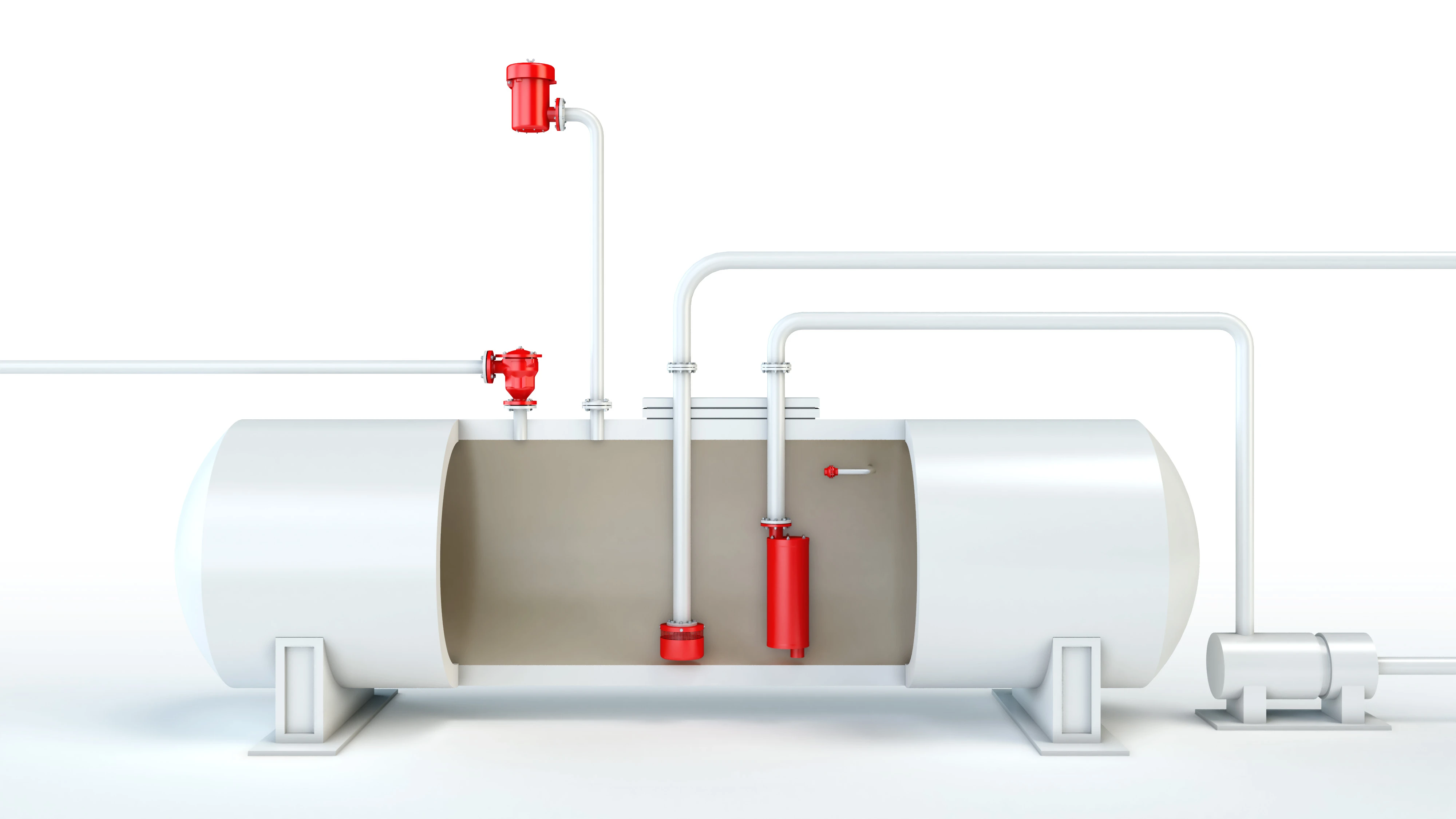
corta-chamas à prova de detonação por produto líquido da série PROTEGO® LDA foi desenvolvido para a tubulação de enchimento de vasos de armazenamento, cuja tubulação não está constantemente cheia com produto e contém temporariamente uma mistura inflamável. O dispositivo é instalado no interior do vaso na extremidade da tubulação e impede que a combustão passe para o tanque em caso de uma ignição da atmosfera explosiva. Os cortachamas à prova de detonação por líquido funcionam pelo princípio de sifão, no qual o produto líquido serve de líquido selante.
Redução da velocidade de propagação de chamas
Na entrada de uma deflagração de tubo muito acelerada ou também detonação, a pressão de combustão e a velocidade de propagação de chamas são primeiro consideravelmente reduzidas pela construção e transformadas em uma deflagração de menor energia, que é depois detida pelo líquido de imersão restante.

Para os grupos de explosão IIA a IIB3
Os limites de utilização do dispositivo em relação às misturas de vapor do produto/ar estão situados a uma temperatura de +60°C e uma pressão de 1,1 bar absoluta. Assim, são abrangidos todos os estados de operação possíveis na prática de tubulações esvaziadas para líquidos inflamáveis. O corta-chamas à prova de detonação por líquido é, por padrão, projetado até 10 bar, sendo assim resistente à pressão de explosão. O dispositivo oferece segurança para quase todos os líquidos inflamáveis e é homologado para os grupos de explosão IIA até IIB3. Teste de protótipo segundo a diretriz ATEX e EN ISO 16852, assim como outras normas internacionais.
Product Data
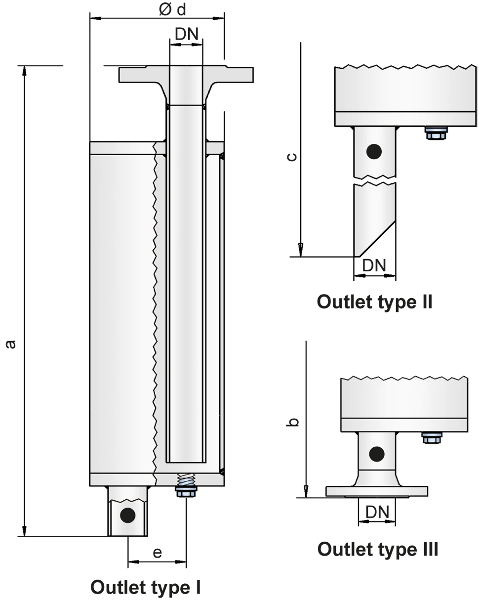
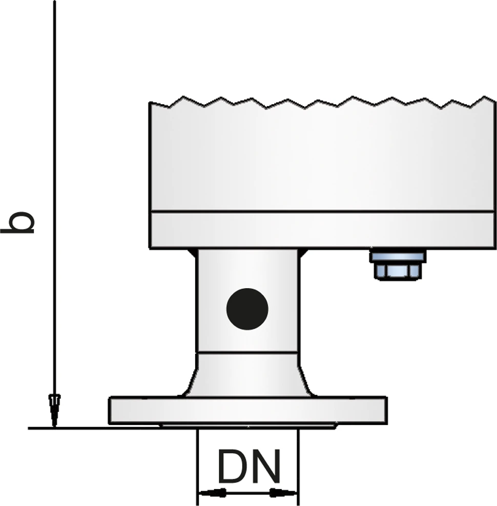
Tabela de dimensões
Para selecionar o diâmetro nominal (DN), veja o diagrama de vazão das páginas seguintes
| DN | 25 / 1" | 32 / 1¼" | 40 / 1½" | 50 / 2" | 65 / 2½" | 80 / 3" | 100 / 4" | 125 / 5" | 150 / 6" | 200 / 8" | 250 / 10" |
| a | 500 | 580 | 700 | 700 | 825 | 925 | 1050 | 1150 | 1350 | 1650 | 2000 |
| b | 538 | 620 | 745 | 745 | 870 | 975 | 1102 | 1205 | 1405 | 1712 | 2068 |
| c | 725 | 805 | 925 | 925 | 1050 | 1145 | 1270 | 1380 | 1580 | 1880 | 2300 |
| d | 115 | 140 | 168 | 168 | 220 | 245 | 325 | 356 | 500 | 600 | 700 |
| e | 50 | 58 | 65 | 65 | 95 | 105 | 135 | 155 | 200 | 250 | 300 |
Dimensões em mm
Seleção do grupo de explosão
| MESG | Gr. expl. (IEC / CEN) | Grupo gás (NEC) |
| > 0,90 mm | IIA | D |
| ≥ 0,65 mm | IIB3 | C |
Aprovações especiais sob solicitação
Indicação da temperatura máx. de trabalho
| ≤ 60°C / 140°F | Ttemperatura máxima de trabalho admissível em °C |
| - | Designation |
temperaturas de trabalho mais elevadas, sob solicitação
Seleção do material do corpo
| Versão | A | B |
| Corpo | aço | aço inoxidável |
| Vedação | WS 3822 | PTFE |
Materiais especiais sob solicitação
Tipo de conexão flangeada
| EN 1092-1; Form B1 |
| ASME B16.5 CL 150 R.F. |
Outras conexões sob solicitação
Outlet type
| Tubo Reto | I |
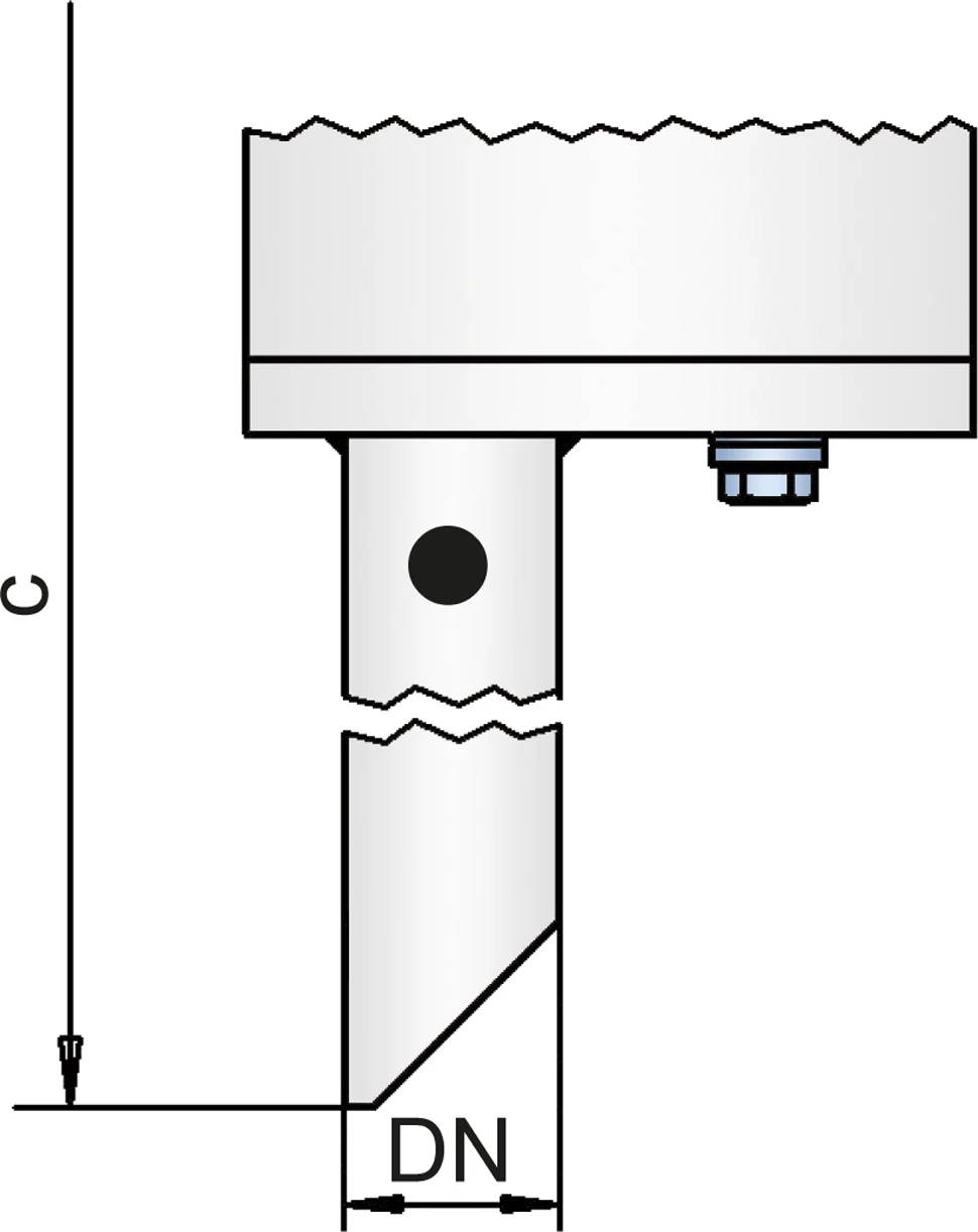
| Tubo chanfrado | II |
| EN 1092-1, Forma B1 ou DIN 2501, Forma C | III (EN bzw. DIN) |
| ASME B16.5 CL 150 R.F. | III (ASME) |
Outras conexões sob solicitação
Diagrama de vazão
A vazão V em m³/h é calculada em conformidade com a norma DIN EN 60534 com a temperatura Tn = 20 °C, uma pressão pn = 1,013 bar e uma viscosidade cinemática v = 10-6 m²/s.
Para evitar a carga eletrostática de líquidos inflamáveis, não deve se ultrapassar uma vazão volumétrica máxima (veja TRGS 727, Relatório CENELEC CLC/TR 60079-32-1).


Se você tiver alguma dúvida, comentário ou sugestão, nossa equipe de especialistas terá prazer em ajudá-lo.
