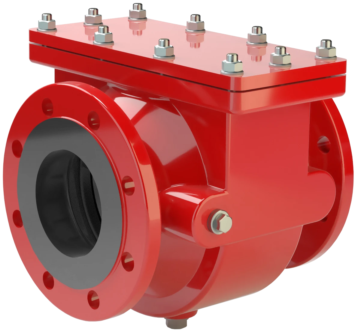
FA-CN-IIC
Corta-chamas à prova de deflagração para tubulação para misturas de hidrogênio/ar, construção concêntrica, de efeito bilateral
Features
Spare Parts
Cost-Effective Spare Parts
Compact Design
Eases Installation Close to Floors and Walls
Modular Design
Allows Replacement and Cleaning of Single FLAMEFILTER®
Bi-Directional Flame Transmission
Proof Design
Provides Safety
Protects Against Deflagrations for All Explosion Groups IIA, IIB3 and IIC (NEC Groups D, C and B)
Any Installation Position
(taking the Set Pressure into Account)
Function and Description
Design compacto e de fácil manutenção
O
Pressure/vacuum relief valve
Pressure/vacuum relief valve is an umbrella term that includes pressure or vacuum relief valve as well as pressure and vacuum relief valve.
corta-chamas à prova de deflagração para tubulação do tipo PROTEGO® FA-CN se caracteriza pelo seu tipo de construção compacto e de manutenção fácil. O tipo de construção especial do PROTEGO® FA-CN-IIC foi desenvolvido para aplicações de hidrogênio do grupo de explosão IIC. O dispositivo se caracteriza especialmente pelos espaçamentos relativamente grandes dos FLAMEFILTER®, relativo ao IIC, que, por um lado, levam a uma reduzida perda de pressão e, por outro, são permeáveis a gotas de líquido pequenas ou partículas. No equipamento de manutenção fácil, o conjunto abafador de chamas PROTEGO® pode ser removido e limpo com poucos movimentos, sem ser necessário desmontar a tubulação.

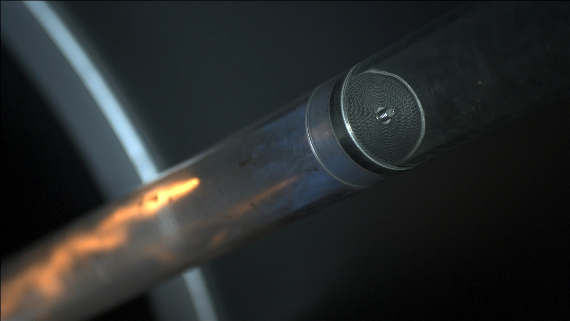
Componente Principal – Conjunto Abafador de Chamas PROTEGO®
Durante a montagem do dispositivo se deve observar que a distância entre a potencial fonte de ignição e o local de instalação do corta-chamas à prova de deflagração para tubulação, a chamada proporção L/D máxima (L/D)máx. (comprimento da tubulação/diâmetro da tubulação), não ultrapasse um determinado valor, dependendo do diâmetro nominal (veja a tabela 4).
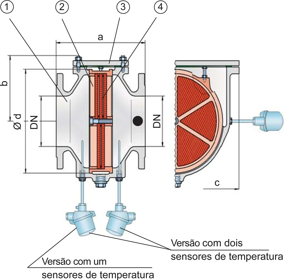
O corta-chamas à prova de deflagração para tubulação é estruturado de forma simétrica e oferece proteção bidirecional contra a propagação de chamas. O dispositivo é composto essencialmente de um corpo (1) com conjunto abafador de chamas PROTEGO® integrado (2) e uma tampa (3). Vários FLAMEFILTER® (4) e espaçadores, encaixados de forma estável em uma armação do FLAMEFILTER®, caracterizam o conjunto abafador de chamas PROTEGO®.
Para o grupo de explosão IIC
O número e o espaçamento dos FLAMEFILTER® são adaptados dependendo das condições de uso do dispositivo de proteção. Os corta-chamas do tipo PROTEGO® FA-CN-IIC oferecem proteção contra deflagrações de misturas de material de combustão/ar do grupo de explosão IIC. Para os equipamentos PROTEGO® FA-CN dos grupos de explosão IIA1, bem como IIA até IIB3, estão disponíveis folhas de dados separadas.
A versão padrão pode ser usada até uma temperatura de trabalho de +60°C e uma pressão de trabalho de 1,1 bar absoluta.

Muitas certificações individuais
Teste de protótipo segundo a diretriz ATEX e EN ISO 16852, assim como outras normas internacionais.
Product Data
Tabela de dimensões
Para selecionar o diâmetro nominal (DN), veja os diagramas de vazão nas páginas seguintes
| DN | 40 / 1½" | 50 / 2" | 65 / 2½" | 80 / 3" | 100 / 4" | 125 / 5" | 150 / 6" | 200 / 8" | 250 / 10" | 300 / 12" |
| a | 210 | 215 | 235 | 240 | 265 | 305 | 310 | 300 | 320 | 350 |
| b | 105 | 105 | 132 | 132 | 150 | 197 | 197 | 220 | 260 | 295 |
| c | 200 | 200 | 260 | 260 | 308 | 415 | 415 | 446 | 520 | 600 |
| d | 130 | 130 | 185 | 185 | 220 | 310 | 310 | 355 | 420 | 490 |
Dimensões em mm
Seleção do grupo de explosão
| MESG | Gr. expl. (IEC / CEN) | Grupo gás (NEC) |
| < 0,50 mm | IIC | B |
Aprovações especiais sob solicitação
Seleção da pressão máx. de trabalho
| DN | 40 / 1½" | 50 / 2" | 65 / 2½" | 80 / 3" | 100 / 4" | 125 / 5" | 150 / 6" | 200 / 8'' | 250 / 10'' | 300 / 12'' |
| Pmax | 1,1 | 1,1 | 1,1 | 1,1 | 1,1 | 1,1 | 1,1 | 1,1 | 1,1 | 1,1 |
Pmáx. = pressão de trabalho máxima admissível em bar absoluta, pressão de trabalho mais elevada sob solicitação
Proporção L/D máxima
| DN | 40 / 1½" | 50 / 2" | 65 / 2½" | 80 / 3" | 100 / 4" | 125 / 5" | 150 / 6" | 200 / 8'' | 250 / 10'' | 300 / 12'' |
| (L / D)max | 30 | 30 | 10 | 10 | 10 | 20 | 20 | 10 | 10 | 5 |
| Identificação | - | - | X12 | X12 | X12 | X10 | X10 | X12 | X12 | X13 |
Seleção do material
| Execução | A | B |
| Corpo | Aço | Aço inoxidável |
| Tampa | Aço | Aço inoxidável |
| Vedação | PTFE | PTFE |
| Conjunto abafador de chamas | Aço inoxidável | Aço inoxidável |
Materiais especiais sob solicitação
Tipo de conexão flangeada
| EN 1092-1; Form B1 |
| ASME B16.5 CL 150 R.F. |
Outras conexões sob solicitação
Diagrama de vazão
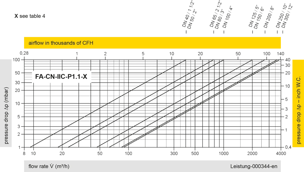
Este diagrama de vazão foi determinado em uma bancada de medição de vazão calibrada e certificada pela TÜV. A vazão V em m³/h se refere ao estado técnico padrão de ar, conforme ISO 6358 (20°C, 1bar). Para conversão em outras densidades e temperaturas, veja o cap. 1: Bases técnicas.


Se você tiver alguma dúvida, comentário ou sugestão, nossa equipe de especialistas terá prazer em ajudá-lo.
