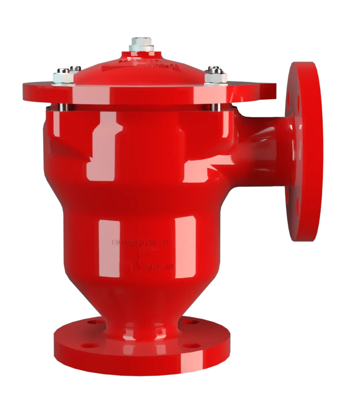
DR/EU
Corta-chamas à prova de detonação em linha para detonações instáveis e estáveis, bem como deflagrações em Versão angular com absorvedor de choque, de efeito unilateral
Features
Reduced Number of FLAMEFILTER® Discs
Fastest Disassembly and Assembly
Modular Design
Angle Bodied
Spare Parts
Provides Safety
Extended Application Range
Low Costs
Protege contra deflagrações e detonações estáveis e instáveis

Componente Principal – Conjunto Abafador de Chamas PROTEGO®

Muitas certificações individuais
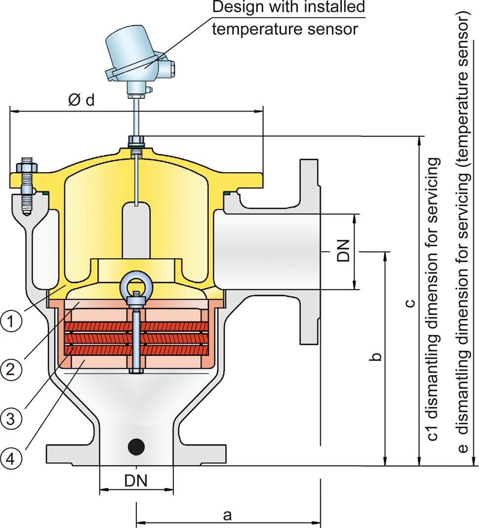
Tabela de dimensões
Para selecionar o diâmetro nominal (DN), utilize os diagramas de vazão nas páginas seguintes
| DN | 25 / 1" | 32 / 1¼" | 40 / 1½" | 50 / 2" | 65 / 2½" | 80 / 3" | 100 / 4" | 125 / 5" | 150 / 6" |
| a | 125 | 125 | 153 | 155 | 198 | 200 | 250 | 332 | 335 |
| b | 140 | 140 | 183 | 185 | 223 | 225 | 290 | 357 | 360 |
| c | 210 | 210 | 290 | 290 | 365 | 365 | 440 | 535 | 535 |
| c1 | 285 | 285 | 395 | 395 | 500 | 500 | 595 | 750 | 750 |
| d | 150 | 150 | 210 | 210 | 275 | 275 | 325 | 460 | 460 |
| e | 495 | 495 | 600 | 600 | 705 | 705 | 795 | 950 | 950 |
Dimensões em mm
Seleção do grupo de explosão
| MESG | Gr. expl. (IEC / CEN) | Grupo gás (NEC) |
| > 0,90 mm | IIA | D |
| ≥ 0,65 mm | IIB3 | C |
Aprovações especiais sob solicitação
Seleção da pressão máx. de trabalho
| Gr. expl. | DN | 25 / 1" | 32 / 1¼" | 40 / 1½" | 50 / 2" | 65 / 2½" | 80 / 3" | 100 / 4" | 125 / 5" | 150 / 6" |
| IIA | Pmax | 1,6 | 1,6 | 1,6 | 1,6 | 1,6 | 1,6 | 1,5 | 1,2 | 1,2 |
| IIB2 | Pmax | 1,4 | 1,4 | |||||||
| IIB3 | Pmax | 1,6 | 1,6 | 1,6 | 1,6 | 1,6 | 1,6 | 1,4 | 1,2* | 1,2* |
Pmáx. = pressão de trabalho máxima admissível em bar absoluta, pressão de trabalho mais elevada sob solicitação, * conjunto abafador de chamas especial
Indicação da temperatura máx. de trabalho
| ≤ 60°C / 140°F | Ttemperatura máxima de trabalho admissível em °C |
| - | Designation |
temperaturas de trabalho mais elevadas, sob solicitação
Seleção do material do corpo
| Versão | B | C | D | |
| Corpo | aço | aço inoxidável | Hastelloy | |
| Camisa de aquecimento (DR / EU-H-(T)-...) | aço | aço inoxidável | aço inoxidável | |
| Tampa com absorvedor de choque | aço | aço inoxidável | Hastelloy | |
| O-Ring | FPM* | PTFE | PTFE | |
| Conjunto abafador de chamas | A | C, D | E | Materiais especiais sob solicitação |
* para equipamentos em caso de aplicação com temperaturas elevadas a partir de 150 °C (T150), vedações em PTFE.
O corpo e a tampa com absorvedor de choque podem ser fornecidos em aço com revestimento de ECTFE.
Combinações de material do conjunto abafador de chamas
| Versão | A | C | D | E |
| Armação do jogo de FLAMEFILTER® | aço | aço inoxidável | aço inoxidável | Hastelloy |
| FLAMEFILTER®* | aço inoxidável | aço inoxidável | Hastelloy | Hastelloy |
| Espaçadores | aço inoxidável | aço inoxidável | Hastelloy | Hastelloy |
* os FLAMEFILTER® também podem ser fornecidos em tântalo, Inconel, cobre, etc. em caso de utilização dos materiais do corpo ou da armação listados.
Materiais especiais sob solicitação
Tipo de conexão flangeada
| EN 1092-1; Form B1 |
| ASME B16.5 CL 150 R.F. |
Diagrama de vazão
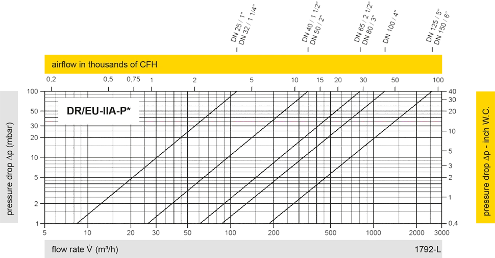
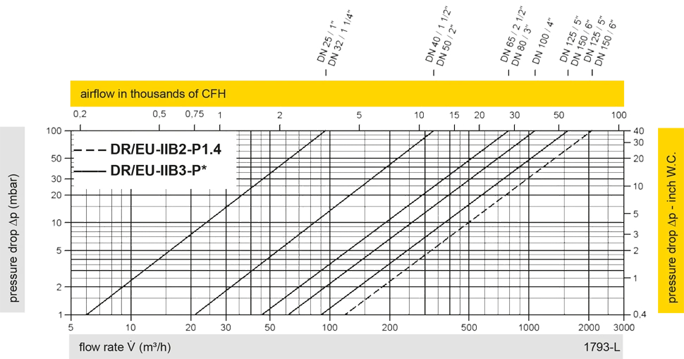
Este diagrama de vazão foi determinado em uma bancada de medição de vazão calibrada e certificada pela TÜV. A vazão V em m³/h se refere ao estado técnico padrão de ar, conforme ISO 6358 (20°C, 1bar). Para conversão em outras densidades e temperaturas, veja o cap. 1: Bases técnicas.


Se você tiver alguma dúvida, comentário ou sugestão, nossa equipe de especialistas terá prazer em ajudá-lo.
