BE/HR-D
Válvula de alívio de pressão à prova de defl agração e combustão contínua
Features
Guided Valve Pallet
Valve Pallet Is Guided Inside the Housing to Protect Against Harsh Weather Conditions
Protective System According to ATEX
can Be Used as a Protective System in Areas With Potentially Explosive Atmosphere in Accordance With ATEX
Extreme Tightness
Resulting in Lowest Possible Product Losses and Reduced Environmental Pollution
Safety Against Endurance Burning
Protection against Atmospheric Deflagration and Endurance Burning
Intergrated Flame Arrester
Integrated PROTEGO® Flame Arrester Unit Saves Space and Weight and Reduces Costs
Flow Capacity
Optimized Flow Capacity
Function and Description
Válvula de alívio de pressão com corta-chama PROTEGO® integrado
A
Pressure/vacuum relief valve
Pressure/vacuum relief valve is an umbrella term that includes pressure or vacuum relief valve as well as pressure and vacuum relief valve.
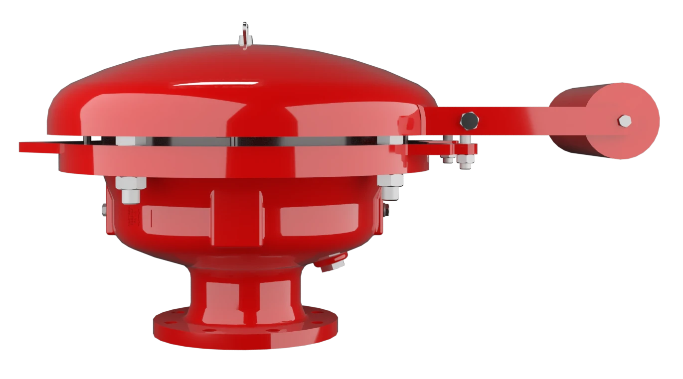
válvula à prova de deflagração e combustão contínua do tipo PROTEGO® BE/HR-D é uma válvula de alívio de pressão altamente desenvolvida com conjunto abafador de chamas integrado PROTEGO® . Ela é principalmente usada como dispositivo de segurança para a expiração à prova de propagação de chamas de tanques, reservatórios e aparelhos de processo. A válvula, por um lado, oferece uma proteção segura contra sobrepressão ou impede a perda inadmissível de produtos até perto da pressão de ajuste e, por outro lado, garante segurança contra propagação de chamas em casos de defl agrações atmosféricas e de queima de longa duração - combustão contínua. O conjunto abafador de chamas PROTEGO® está configurado de tal forma, que seja atingido um mínimo de perda de pressão com máxima segurança. A válvula PROTEGO® BE/HR-D está disponível para substâncias do grupo de explosão IIA.
Tecnologia avançada de manufatura
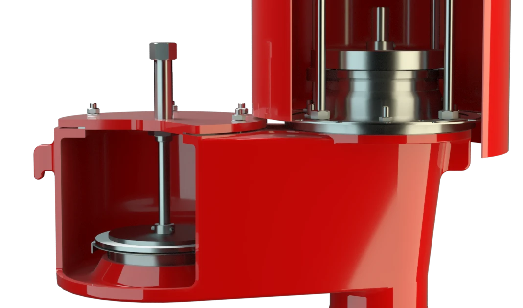
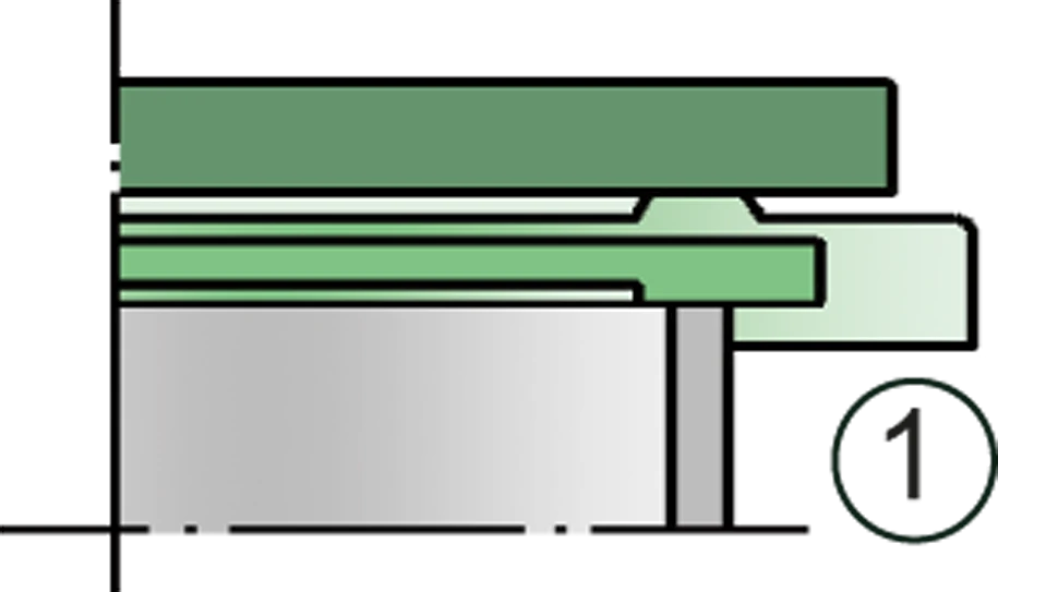
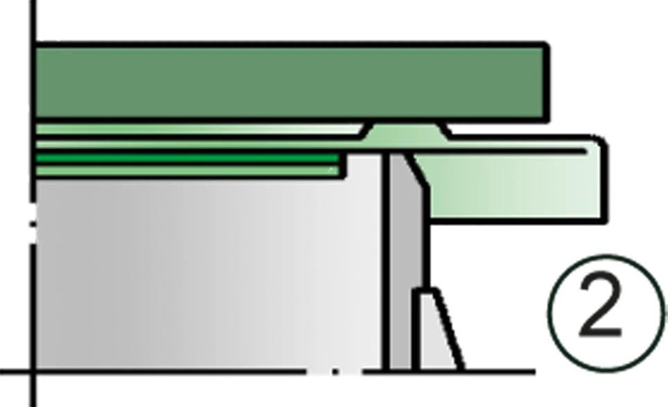
Ao alcançar a pressão de ajuste a válvula inicia a abertura e atinge a pressão de abertura dentro de um aumento de pressão de 40%. Até alcançar a pressão de ajuste, garante-se a conservação de pressão do tanque com uma estanqueidade muito acima do padrão normal graças à tecnologia de fabricação altamente desenvolvida. Esta característica se obtém também com sedes de válvulas fabricadas em aço inoxidável de alta qualidade e obturadores da válvula individualmente lapidados (1) ou com vedação de colchão de ar com selo de FEP de alta qualidade (2). Depois de aliviar a sobrepressão, a válvula fecha novamente e permanece estanque.

Muitas certificações individuais
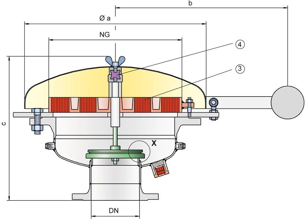
Se a pressão de ajuste ajustada for ultrapassada, escapam misturas explosivas de gases/ar respectivamente de vapor de produto/ ar. Se estas misturas entrarem em ignição, o conjunto abafador de chamas PROTEGO® (3) integrado impede um retrocesso de ignição ao tanque. Se seguir mais mistura, o conjunto abafador de chamas PROTEGO® resiste a uma combustão contínua. Através disto a válvula está protegida e atende a sua função também em caso de uma combustão contínua. A tampa de proteção contra intempéries suspensa por molas abre tão logo o elemento fusível (4) a libere. A válvula pode ser usada até uma temperatura de serviço de +60°C e atende aos requisitos da norma europeia para construção de tanques EN 14015 – Anexo L e ISO 28300 (API 2000). Teste de protótipo segundo a diretriz ATEX e EN ISO 16852, assim como outras normas internacionais.
Product Data
Tabela de dimensões
Para escolher o diâmetro nominal (DN), veja o diagrama de vazão da página seguinte
| DN | 150 / 6" | 200 / 8" |
| NG | 400 / 16" | 400 / 16" |
| a | 600 | 600 |
| b | 545 | 545 |
| c | 485 | 485 |
Dimensões em mm
Seleção do grupo de explosão
| MESG | Gr. expl. (IEC / CEN) | Grupo gás (NEC) |
| > 0,90 mm | IIA | D |
Aprovações especiais sob solicitação
Seleção do material do corpo
| Execução | A | B |
| Corpo | Aço | Aço inoxidável |
| Sede de válvula | Aço inoxidável | Aço inoxidável |
| Tampa | Aço | Aço inoxidável |
| Conjunto abafador de chamas | A | B |
Materiais especiais sob solicitação
Combinações de material do conjunto abafador de chamas
| Execução | A | B |
| Armação do FLAMEFILTER® | Aço | Aço inoxidável |
| FLAMEFILTER® | Aço inoxidável | Aço inoxidável |
Materiais especiais sob solicitação
Seleção de material do obturador da válvula
| Execução | A | B | C |
| Faixa de pressão [mbar] | +2.0 até +3.5 | >+3.5até +14 | >+14até +35 |
| Obturador da válvula | Alumínio | Aço inoxidável | Aço inoxidável |
| Vedação | FEP | FEP | metálica |
Materiais especiais e ajustes de pressões mais altas sob solicitação
Tipo de conexão flangeada
| EN 1092-1; Form B1 |
| ASME B16.5 CL 150 R.F. |
Outras conexões sob solicitação
Diagrama de vazão
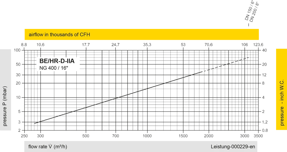
Este diagrama de vazão foi determinado em uma bancada de medição de vazão calibrada e certificada pela TÜV. A vazão V em m³/h se refere ao estado técnico padrão de ar, conforme ISO 6358 (20°C, 1bar). Para conversão em outras densidades e temperaturas, veja o cap. 1: Bases técnicas.
Detalhe X
Detalhe X


Se você tiver alguma dúvida, comentário ou sugestão, nossa equipe de especialistas terá prazer em ajudá-lo.
