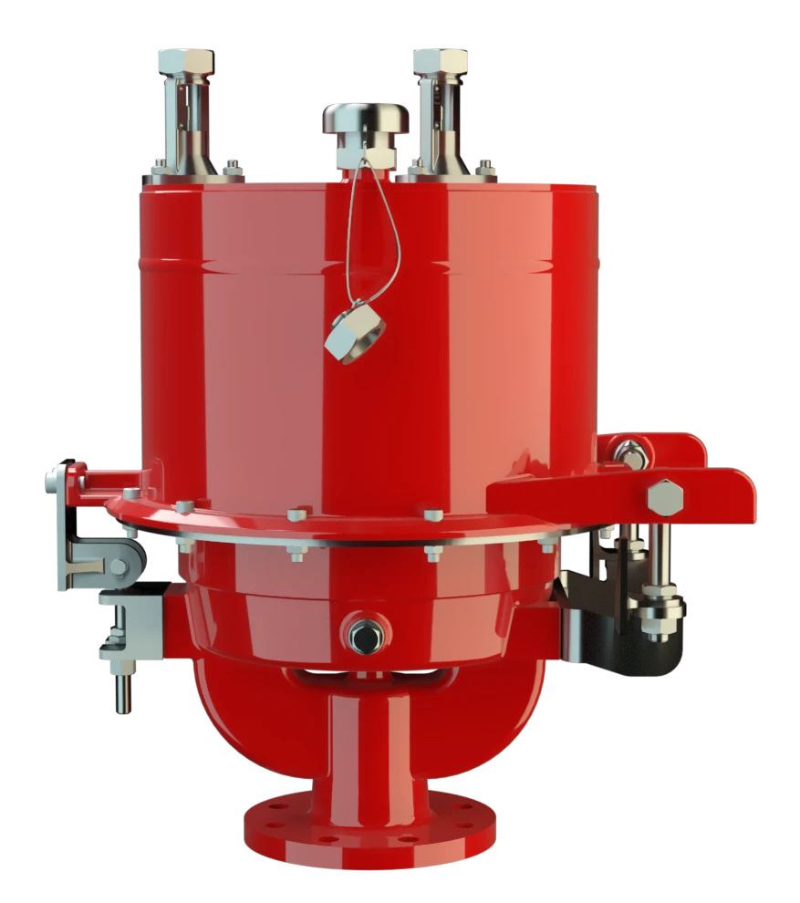
UB/SF-G
Válvula de alívio de pressão e vácuo de diafragma à prova de deflagração e combustão contínua
Features
Suitable for Challenging Applications
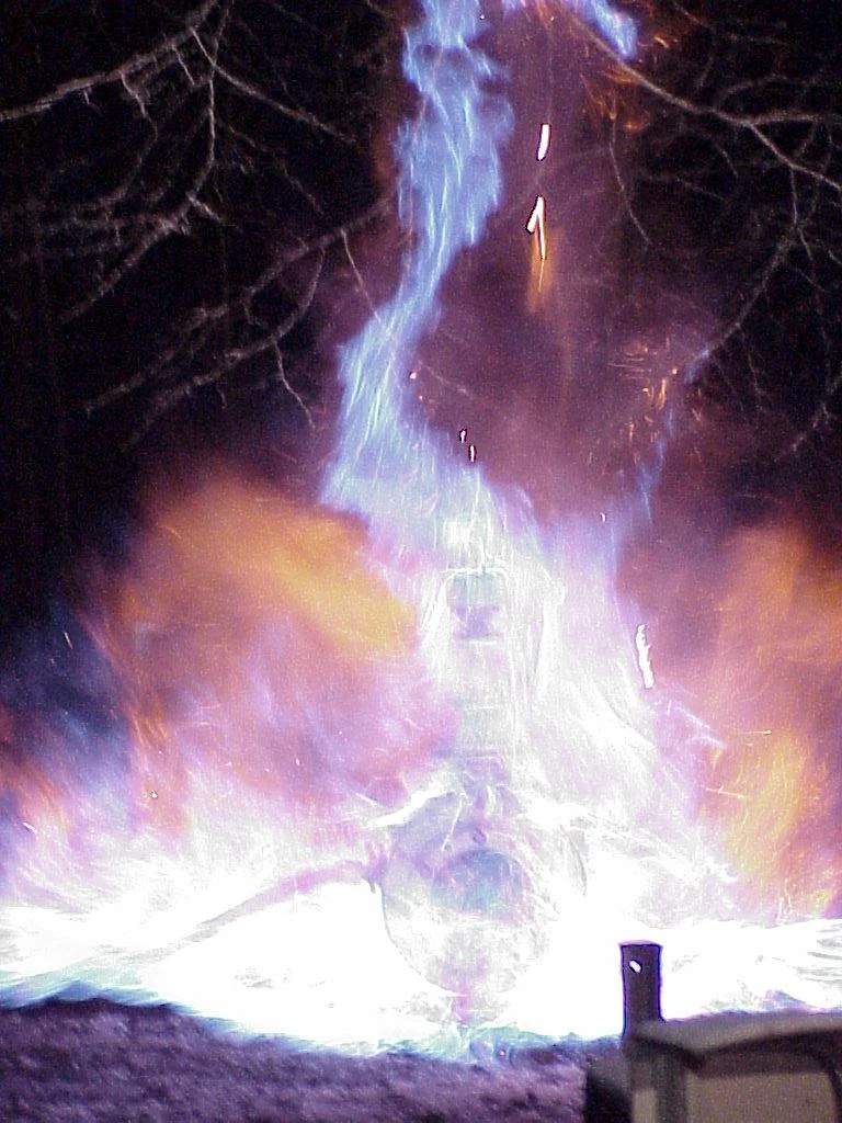
Safety Against Endurance Burning
Extreme Tightness
Digital Level Monitoring
Digital Level Sensors
Safe Venting
Frost-Proof
Condensate Drainage
Monitoring
Modular Design
Easy Operation Monitoring
Protective System According to ATEX
Optimal Pressure Maintenance
Válvula combinada de alívio de pressão e vácuo
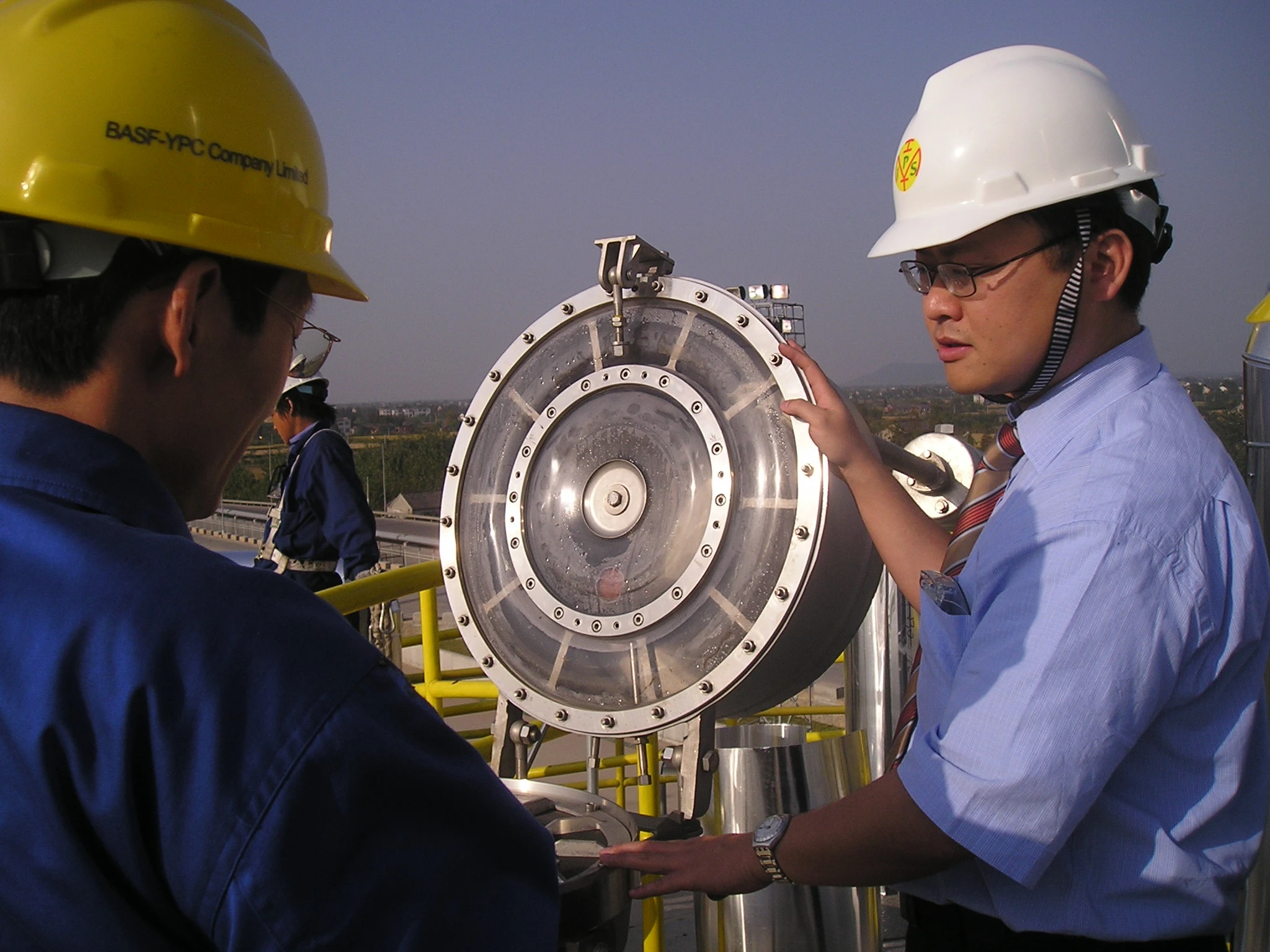
Alta confiabilidade operacional em condições extremas
Para o grupo de explosão IIB3
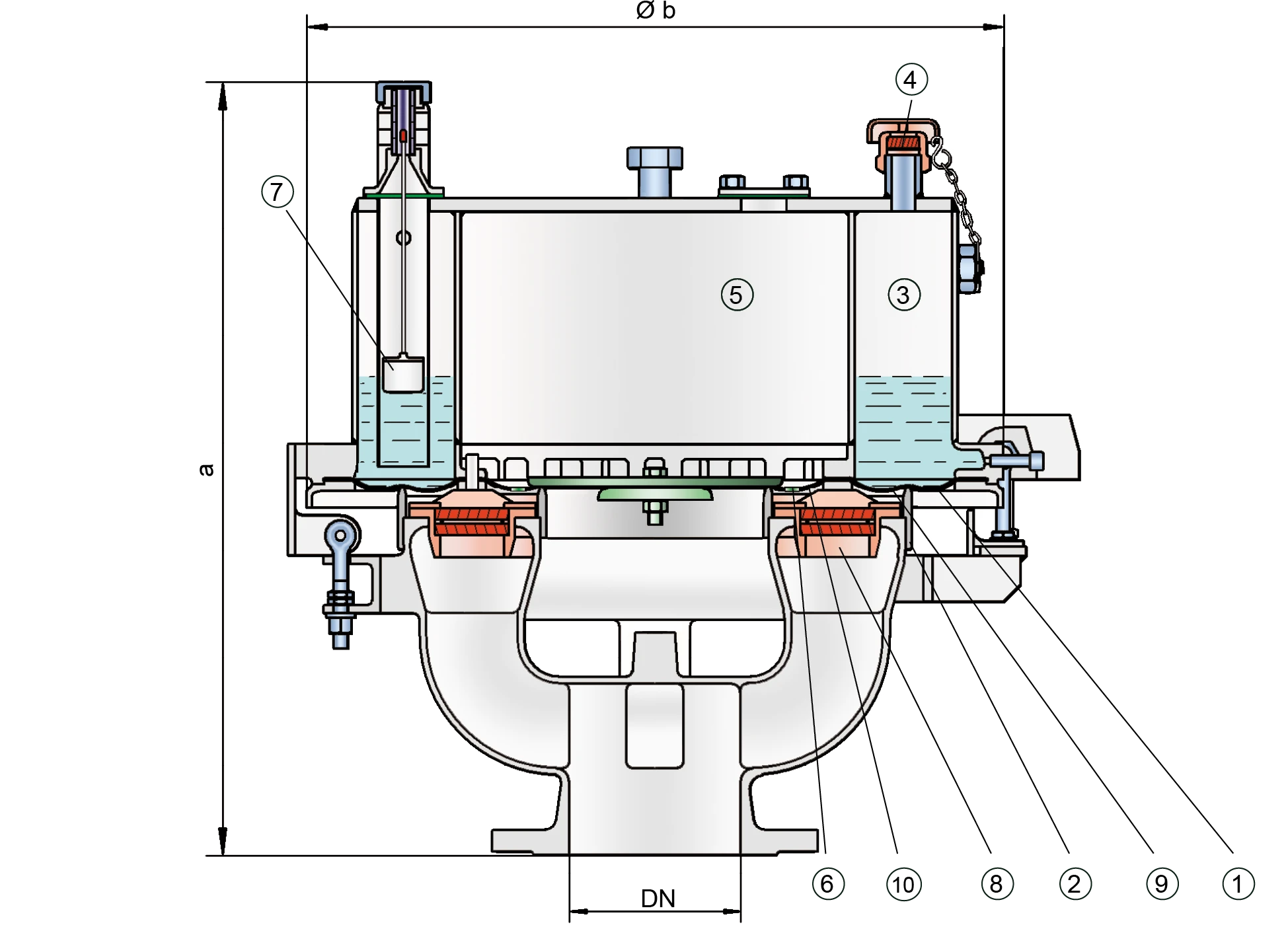
Composição
Tecnologia avançada de vedação e supressão dinâmica de chamas em válvula de alívio de sobrepressão
Componente Principal – Conjunto Abafador de Chamas PROTEGO®
Muitas certificações individuais
Tabela de dimensões
Para escolher o diâmetro nominal (DN), veja os diagramas de vazão nas páginas seguintes
| DN | Pressão | 80 / 3" | Pressão | 100 / 4" | Pressão | 150 / 6" |
| a | até +28 mbar | 615 | até +28 mbar | 645 | até +25 mbar | 680 |
| a | > +28 mbar | 765 | > +28 mbar | 795 | > +25 mbar | 830 |
| b | 410 | 485 | 590 |
Dimensões em mm
Ajustes de pressão > +50 mbar (DN 80), > +45 (DN 100), > +46 (DN 150) com dimensões de construção de guarnição adicional sob solicitação
Dimensões de construção para a válvula de alívio de pressão e de vácuo de diafragma com serpentina de aquecimento sob solicitação
Seleção do grupo de explosão
| MESG | Gr. expl. (IEC / CEN) | Grupo gás (NEC) |
| ≥ 0,65 mm | IIB3 | C |
Aprovações especiais sob solicitação
Seleção do material do corpo
| Execução | C | D |
| Corpo | Aço | Aço inoxidável |
| Parte superior da válvula | Aço inoxidável | Aço inoxidável |
| Serpentina de aquecimento (UB / SF-H-...) | Aço inoxidável | Aço inoxidável |
| Sedes de válvulas | Aço inoxidável | Aço inoxidável |
| Vedação | FPM | PTFE |
| Diafragma | A, B | A, B |
| Conjunto abafador de chamas | C | C |
Os corpos também podem ser fornecidos com revestimento de ECTFE
Materiais especiais sob solicitação
Seleção do material
| Execução | A | B |
| Diafragma | FPM | FEP |
Materiais especiais sob solicitação
Combinações de material do conjunto abafador de chamas
| Execução | A | C |
| Armação do FLAMEFILTER® | Ferro fundido | Aço inoxidável |
| FLAMEFILTER® | Aço inoxidável | Aço inoxidável |
| Espaçador | Aço inoxidável | Aço inoxidável |
Materiais especiais sob solicitação
Tipo de conexão flangeada
| EN 1092-1; Form B1 |
| ASME B16.5 CL 150 R.F. |
Outras conexões sob solicitação
Diagrama de vazão
UB/SF-G DN100 pressure
UB/SF-G DN150 pressure
UB/SF-G DN80 vacuum
UB/SF-G DN100 vacuum
UB/SF-G DN150 vacuum
Este diagrama de vazão foi determinado em uma bancada de medição de vazão calibrada e certificada pela TÜV. A vazão V em m³/h se refere ao estado técnico padrão de ar, conforme ISO 6358 (20°C, 1bar). Para conversão em outras densidades e temperaturas, veja o cap. 1: Bases técnicas.


Se você tiver alguma dúvida, comentário ou sugestão, nossa equipe de especialistas terá prazer em ajudá-lo.
