VN-A-PCPM
Válvula de alívio de pressão e vácuo Válvula piloto-operada com diafragma
Features
Permanent Magnets
Controlled by Corrosion-Resistant Control Valve (Pilot Valve), Low-Temperature-Resistant Permanent Magnet
Pop-Open Characteristic
from the Lowest Pressure Increase up to Full Lift
Extreme Tightness
Resulting in Lowest Possible Product Losses and Reduced Environmental Pollution
10% Technology
for Minimum Pressure Increase up to Full Lift
Optimal Pressure Maintenance
Set Pressure Close to Opening Pressure for Optimum Pressure Maintenance in the System
Flow Capacity
Optimized Flow Capacity
High Durability
Protection of the Main Valve Control Diaphragm From Low Temperatures – High Durability
Used in Explosion Hazardous Areas
can Be Used in Explosion Hazardous Areas
Low Temperature
Designed for Use at Low Temperatures
Condensate Drainage
Automatic Condensate Drain
Field Test Kit
Field Test and Kit Connection Possible Upon Request
Function and Description
Válvula combinada de alívio de pressão e vácuo
A
Pressure/vacuum relief valve
Pressure/vacuum relief valve is an umbrella term that includes pressure or vacuum relief valve as well as pressure and vacuum relief valve.
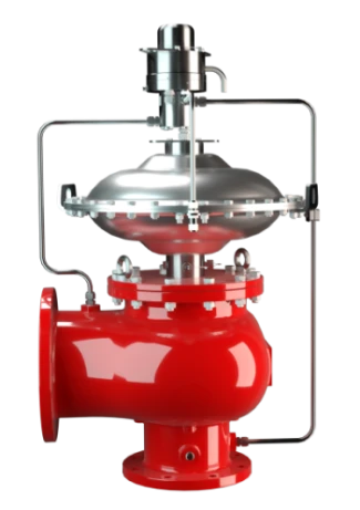
válvula piloto-operada com diafragma do tipo PROTEGO® PM/(D)S é uma válvula combinada de alívio de pressão e vácuo altamente desenvolvida. Ela é principalmente usada como dispositivo de segurança para a expiração de tanques, vasos e aparelhos de processos para protegê-los de excessos de pressão inadmissíveis. Evitam-se emissões até alcançar a pressão de ajuste. A válvula também pode ser utilizada para a aspiração. Nisso, a válvula principal atua diretamente no caso de vácuo, ou seja, funciona como uma válvula de diafragma calibrada por peso. Esta válvula é perfeitamente adequada para o uso em condições atmosféricas, como também em baixas temperaturas climáticas.
Estanqueidade extrema
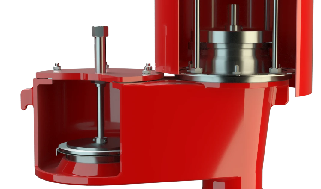
O controle da válvula principal é realizado com uma válvula piloto. A válvula piloto é controlada pela pressão no tanque sem fluxo constante da substância do tanque no piloto. A pressão de ajuste é regulada na válvula piloto através de um ímã permanente resistente a corrosão e a baixas temperaturas.
O aumento da pressão de trabalho intensifica a força de vedação da válvula principal, ou seja, a estanqueidade da válvula é aumentada até alcançar a pressão de ajuste determinada, impedindo perdas de pequena quantidade. Após alcançar a pressão de ajuste, a válvula abre a curso pleno sem um aumento significativo da pressão (característica de abertura brusca) e realiza a vazão necessária com válvula totalmente aberta. Se essa for excedida, o aumento de pressão segue a curva de vazão (curva Δp/V..).
Tecnologia avançada de manufatura
Até alcançar a pressão de ajuste, garante-se a conservação da pressão do tanque com uma estanqueidade muito acima do padrão normal graças a tecnologia de fabricação altamente desenvolvida. Esta característica se obtém por exemplo, com sedes de válvulas em aço inoxidável de alta qualidade e obturadores de válvulas individualmente lapidados. Depois de aliviar o excesso de pressão ou compensar o vácuo, a válvula fecha e proporciona uma vedação firme.
Product Data
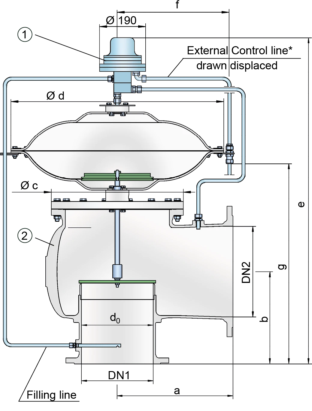
Tabela de dimensões
Para escolher o diâmetro nominal (DN), veja os diagramas de vazão nas páginas seguintes
| DN1 | 80 / 3" | 100 / 4" | 150 / 6" | 200 / 8" | 250 / 10" | 300 / 12" | 300 / 12" |
| DN2 | 100 / 4" | 150 / 6" | 200 / 8" | 250 / 10" | 300 / 12" | 350 / 14" | 400 / 16" |
| a | 225 | 250 | 325 | 375 | 450 | 500 | 500 |
| b | 150 | 175 | 225 | 250 | 270 | 300 | 325 |
| c | 275 | 330 | 445 | 550 | 665 | 785 | 785 |
| d | 370 | 425 | 530 | 605 | 675 | 785 | 835 |
| e | 615 | 685 | 770 | 825 | 935 | 1005 | 1055 |
| f | 35 | 40 | 40 | 50 | 50 | 50 | 50 |
| g | 160 | 195 | 250 | 315 | 370 | 425 | 425 |
| DN1 | 80 / 3" | 100 / 4" | 150 / 6" | 200 / 8" | 250 / 10" | 300 / 12" | 300 / 12" |
| DN2 | 100 / 4" | 150 / 6" | 200 / 8" | 250 / 10" | 300 / 12" | 350 / 14" | 400 / 16" |
| d0 | 81 | 107 | 160 | 208 | 260 | 310 | 310 |
| K | 0,68 | 0,6 | 0,59 | 0,59 | 0,56 | 0,53 | 0,61 |
| Kdr | |||||||
| 90% | 0,61 | 0,54 | 0,53 | 0,53 | 0,5 | 0,48 | 0,55 |
| Kdr | |||||||
| 95% | 0,65 | 0,57 | 0,56 | 0,56 | 0,53 | 0,5 | 0,58 |
Dimensões em mm
Seleção do material do corpo
| Execução | A | B |
| Corpo | Alumínio | Aço inoxidável |
| Sedes de válvulas | Aço inoxidável | Aço inoxidável |
| Vedação | KL-C-4106 | KL-C-4106 |
| Proteção do diafragma principal | Aço inoxidável | Aço inoxidável |
| Tubos de comando | Aço inoxidável | Aço inoxidável |
| Corpo da unidade piloto | Aço inoxidável | Aço inoxidável |
| Diafragma piloto | FEP | FEP |
Materiais especiais sob solicitação
Tipo de conexão flangeada
| EN 1092-1; Form B1 |
| ASME B16.5 CL 150 R.F. |
Other types upon request
Coefficient of Discharge
| DN1 | 50 / 2" | 50 / 2" | 80 / 3" | 80 / 3" | 100 / 4" | 100 / 4" | 150 / 6" | 150 / 6" | 200 / 8" | 200 / 8" | 250 / 10" | 250 / 10" | 300 / 12" | 300 / 12" | 300 / 12" |
| DN2 | 50 / 2" | 80 / 3" | 80 / 3" | 100 / 4" | 100 / 4" | 150 / 6" | 150 / 6" | 200 / 8" | 200 / 8" | 250 / 10" | 250 / 10" | 300 / 12" | 300 / 12" | 350 / 14" | 400 / 16" |
| d0 | 54 / 2.13 | 54 / 2.13 | 83 / 3.27 | 83 / 3.27 | 108 / 4.25 | 108 / 4.25 | 160 / 6.30 | 160 / 6.30 | 208 / 8.19 | 208 / 8.19 | 262 / 10.31 | 262 / 10.31 | 310 / 12.20 | 310 / 12.20 | 310 / 12.20 |
| K | 0.57 | 0.75 | 0.63 | 0.71 | 0.60 | 0.75 | 0.64 | 0.78 | 0.63 | 0.76 | 0.62 | 0.73 | 0.63 | 0.68 | 0.74 |
DN1 = size inlet
DN2 = size outlet
d0 = orifice diameter(mm / inches)
K = coefficient of discharge
Diagrama de vazão
Este diagrama de vazão foi determinado em uma bancada de medição de vazão calibrada e certificada pela TÜV. A vazão V em m³/h se refere ao estado técnico padrão de ar, conforme ISO 6358 (20°C, 1bar). Para conversão em outras densidades e temperaturas, veja o cap. 1: Bases técnicas.
Applications
Se você tiver alguma dúvida, comentário ou sugestão, nossa equipe de especialistas terá prazer em ajudá-lo.
