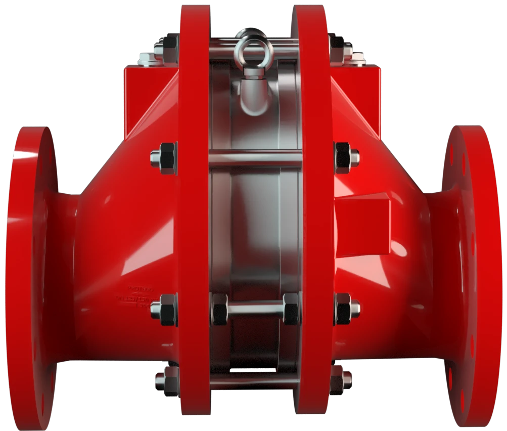
FA-E
In-Line Deflagration Flame Arrester eccentric design, bidirectional
Features
Eccentric Design
Versatile Application Options
Bi-Directional Flame Transmission
Modular Design
Provides Safety
Spare Parts
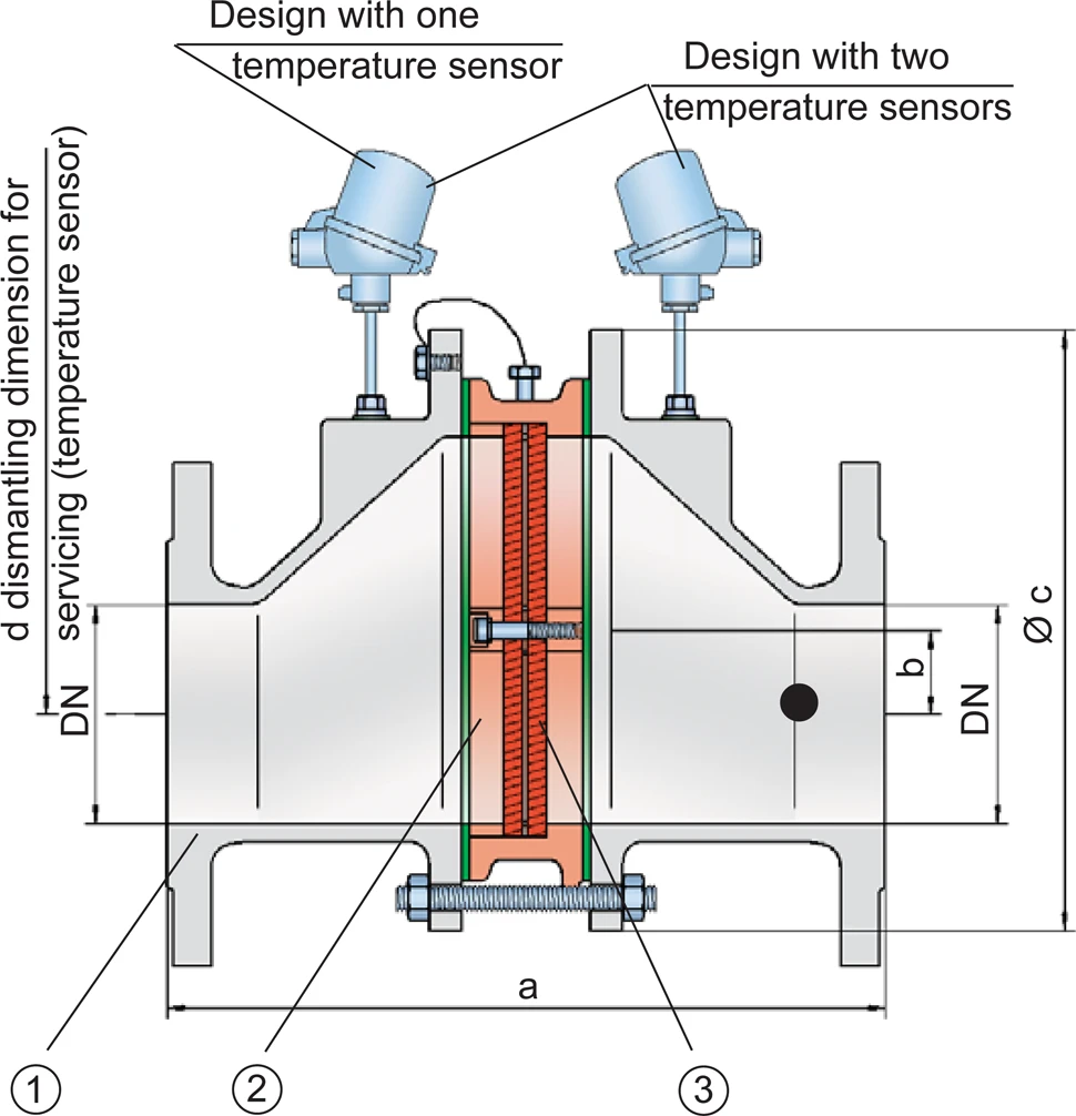
Excentric Design

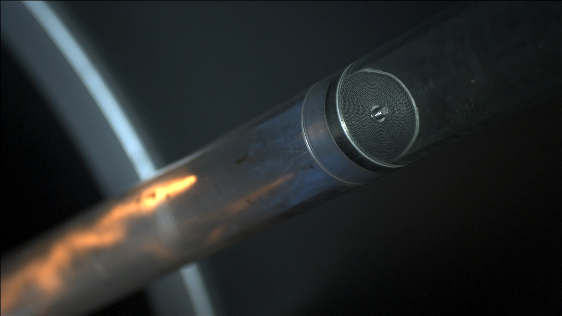
Main Component – PROTEGO® Flame Arrester Unit
For Explosion Group IIA to IIC

Many Individual Certifications
Dimensions
To select the nominal size Nennweite The nominal size is an alphanumeric designation of size for components in a piping system, used for reference purposes, comprising the letters DN followed by a dimensionless integer that is indirectly related to the physical size of the bore or outside diameter of the connections, expessed in millimeters. (DN), use the flow capacity charts on the following pages
| Expl. Gr. | DN | 25 / 1" | 32 / 1¼“ | 40 / 1½“ | 50 / 2" | 65 / 2½“ | 80 / 3" | 100 / 4" | 125 / 5" | 150 / 6" | 200 / 8" | 250 / 10" | 300 / 12" |
| IIA | a | 304 / 11.97 | 304 / 11.97 | 310 / 12.20 | 314 / 12.36 | 360 / 14.17 | 364 / 14.33 | 370 / 14.57 | 434 / 17.09 | 440 / 17.32 | 450 / 17.72 | 480 / 18.90 | 500 / 19.69 |
| IIB3 | a | 304 / 11.97 | 304 / 11.97 | 310 / 12.20 | 314 / 12.36 | 360 / 14.17 | 364 / 14.33 | 370 / 14.57 | 434 / 17.09 | 440 / 17.32 | 450 / 17.72 | 480 / 18.90 | 500 / 19.69 |
| IIC | a | 304 / 11.97 | 304 / 11.97 | 321 / 12.64 | 325 / 12.80 | 371 / 14.61 | 375 / 10.83 | 381 / 15.00 | 445 / 17.52 | 451 / 17.76 | 461 / 18.15 | 491 / 19.33 | 511 / 20.12 |
| b | 29 / 1.14 | 29 / 1.14 | 29 / 1.14 | 29 / 1.14 | 38 / 1.49 | 38 / 1.49 | 39 / 1.53 | 65 / 2.56 | 65 / 2.56 | 55 / 2.17 | 58 / 2.28 | 60 / 2.36 | |
| c | 185 / 7.28 | 185 / 7.28 | 210 / 8.27 | 210 / 8.27 | 250 / 9.84 | 250 / 9.84 | 275 / 10.83 | 385 / 15.16 | 385 / 15.16 | 450 / 17.72 | 500 / 19.69 | 575 / 22.64 | |
| d | 400 / 15.75 | 400 / 15.75 | 410 / 16.14 | 410 / 16.14 | 440 / 17.32 | 440 / 17.32 | 460 / 18.11 | 520 / 20.47 | 520 / 20.47 | 540 / 21.26 | 570 / 22.44 | 600 / 23.62 |
Dimensions in mm / inches
Selection of explosion group
| MESG | Expl. Gr. (IEC / CEN) | Gas Group (NEC) |
| > 0,90 mm | IIA | D |
| ≥ 0,65 mm | IIB3 | C |
| < 0,50 mm (> 0,50 mm) | IIC (IIB) | B |
Special approvals upon request
Selection of max. operating pressure
| Expl. Gr. | DN | 25 / 1" | 32 / ¼" | 40 / 1½" | 50 / 2" | 65 / 2½" | 80 / 3" | 100 / 4" | 125 / 5" | 150 / 6" | 200 / 8" | 250 / 10" | 300 / 12" |
| IIA | Pmax | 1,6 / 23.2 | 1,6 / 23.2 | 1,6 / 23.2 | 1,6 / 23.2 | 1,6 / 23.2 | 1,6 / 23.2 | 1,6 / 23.2 | 1,6 / 23.2 | 1,6 / 23.2 | 1,6 / 23.2 | 1,6 / 23.2 | 1,6 / 23.3 |
| IIB3 | Pmax | 1,6 / 23.3 | 1,6 / 23.3 | 1,6 / 23.3 | 1,6 / 23.3 | 1,6 / 23.3 | 1,6 / 23.3 | 1,6 / 23.3 | 1,6 / 23.3 | 1,6 / 23.3 | 1,6 / 23.3 | 1,6 / 23.3 | 1,6 / 23.3 |
| IIC | Pmax | 1,1 / 15.9 | 1,1 / 15.9 | 1,1 / 15.9 | 1,1 / 15.9 | 1,1 / 15.9 | 1,1 / 15.9 | 1,2 / 15.9 | 1,1 / 15.9 | 1,1 / 15.9 | 1,1 / 15.9 | 1,1 / 15.9 | 1,1 / 15.9 |
Pmax = maximum allwowable operating pressure in bar / psi (absolute), higher operating pressure upon request
Specification of max. operating temperature
| ≤ 60°C / 140°F | Tmaximum allowable operating temperature in °C |
| - | Designation |
higher operating temperatures upon request
Material selection for housing
| Design | B | C | D |
| Housing | Steel | Stainless Steel | Hastelloy |
| Gasket | PTFE | PTFE | PTFE |
| Flame arrester unit | A,C | C | D |
The housing can also be delivered in carbon steel with an ECTFE coating Beschichtung Coating is the application of a firmly adhering layer of shapeless material to the surface of a workpiece. .
Special materials upon request
Material combinations of flame arrester unit
| Design | A | C | D |
| FLAMEFILTER® cage | Steel | Stainless Steel | Hastelloy |
| FLAMEFILTER®* | Stainless Steel | Stainless Steel | Hastelloy |
| Spacers | Stainless Steel | Stainless Steel | Hastelloy |
*the FLAMEFILTER® is also available in the materials Tantalum, Inconel, Copper, etc. when the listed housing and cage materials are used
Special materials upon request.
Flange connection type
| EN 1092-1; Form B1 |
| ASME B16.5 CL 150 R.F. |
other connections upon request
Flow Capacity Chart
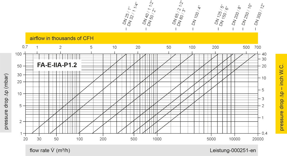
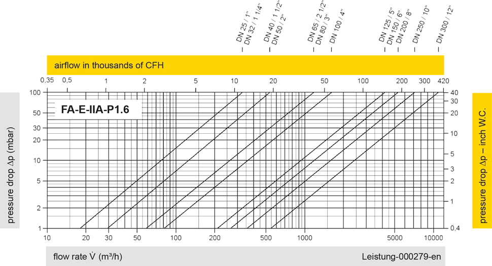
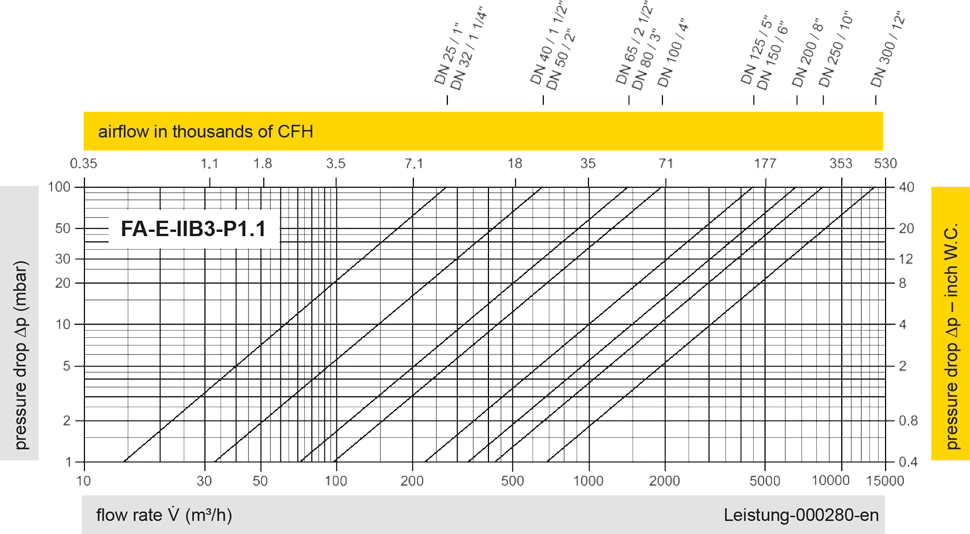
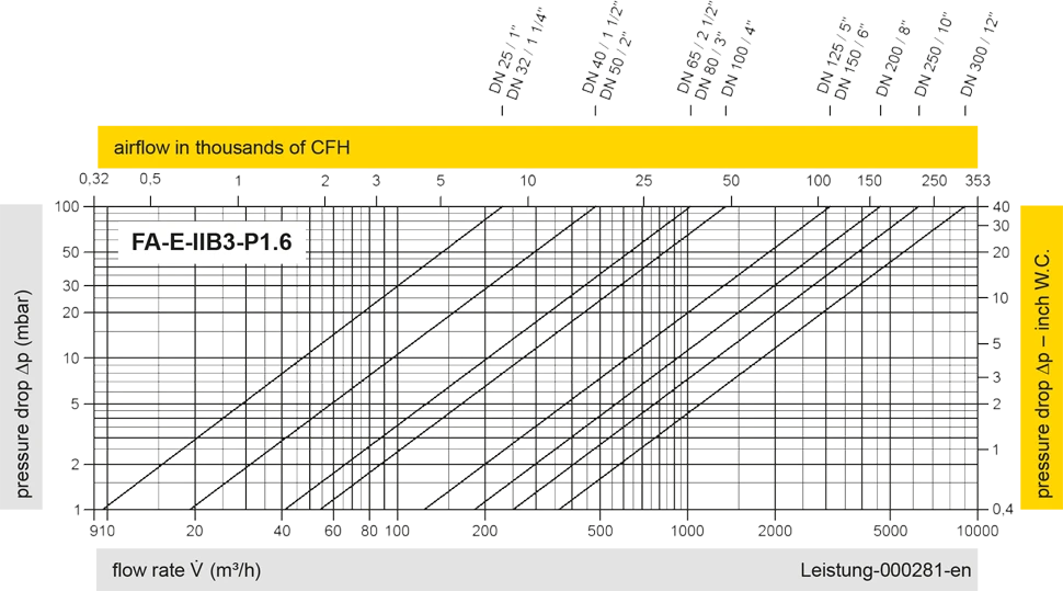
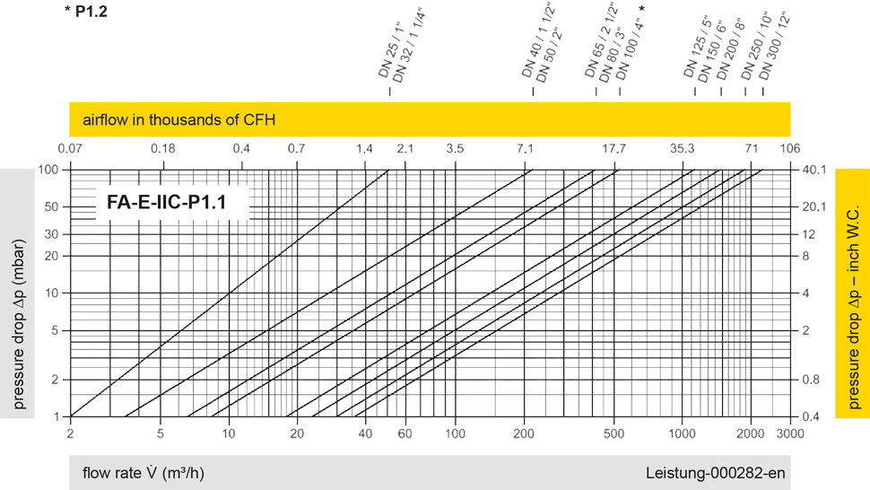
The flow capacity charts have been determined with a calibrated and TÜV certified flow capacity test rig. Volume flow V in (m³/h) and CFH refer to the standard reference conditions of air ISO 6358 (20°C, 1bar). For conversion to other densities and temperatures refer to Sec. 1: “Technical Fundamentals”.


Si vous avez des questions, des commentaires ou des suggestions, notre équipe d'experts se fera un plaisir de vous aider.
